Portland Guitar Co. | Portland Oregon | Contact Jay Dickinson-503.245.3276 | jay@portlandguitar.com
Portland Guitar Pretty Good Intonation (PGPG) System
Finished Build
Orchestral Model Cutaway
Serial # OMC 1.6.41
- Body:.......................... Philippine Ebony
- Top:............................ Sitka Spruce
- Neck:.......................... Khaya (Mahogany)
- Binding:...................... High Figure Snakewood
- Purfling:...................... Fine Herringbone with Green Pinstriping
- Appointments:............ Amboyna Burl, Brazilian Rosewood
- Fretboard & Bridge:.... 24 Nickel-Silver Frets Macassar Ebony with Snakewood Binding
- Tuners:........................Waverly, Nickel Plated with Ebony Knobs
Page 5
 ( 128 ) 24-Jan-2011
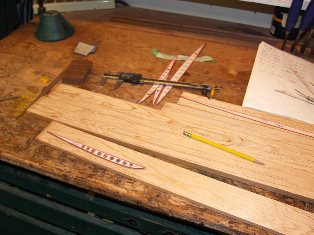
At this point in the build I am turning my attention to the braces for the top and the back. In this image I am laying out the brace templates on some pre-dimensioned pieces of Sitka spruce. Sitka spruce is used for the braces because it is quite light and is very strong. The mass of the braces is a very important factor in the responsiveness of the instrument, generally the less massive the top and the back the more responsive the guitar will be.
 ( 129 ) 24-Jan-2011
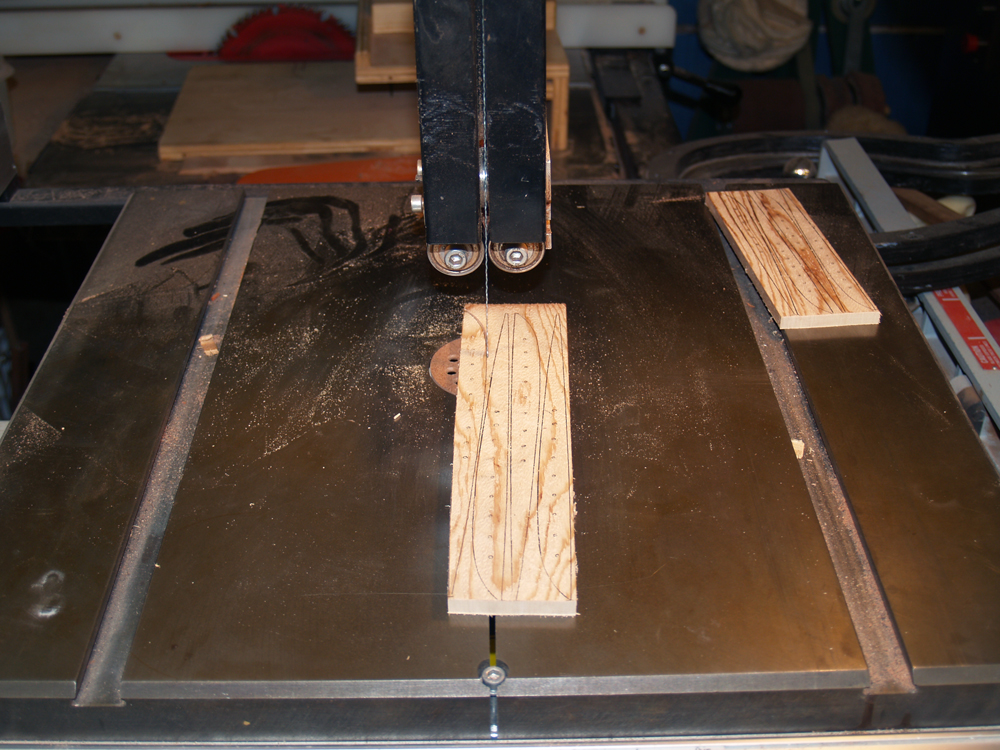
Because the mass of the braces is so important Portland Guitar employes an Engineered Brace System that reduces the mass of each brace by up to 50%. There are quite a few steps in the process to make these braces, but it is well worth the effort. In this picture I am using the band saw to cut out the brace blanks.
 ( 130 ) 24-Jan-2011
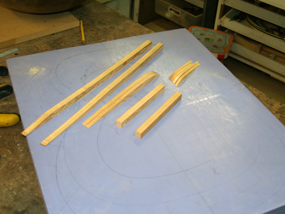
In this picture you can see the set of brace blanks that will be used for the top.
 ( 131 ) 24-Jan-2011
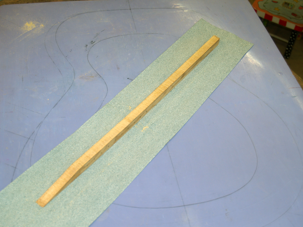
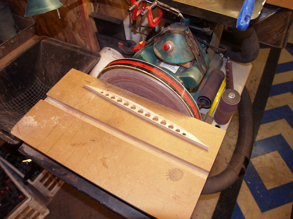
I use the top dish that has the final shape of the top with a piece of sandpaper to match the bottom of the brace to the shape of the dish.
 ( 132 ) 24-Jan-2011
I do the same thing with the brace blanks used for the back.
 ( 133 ) 24-Jan-2011
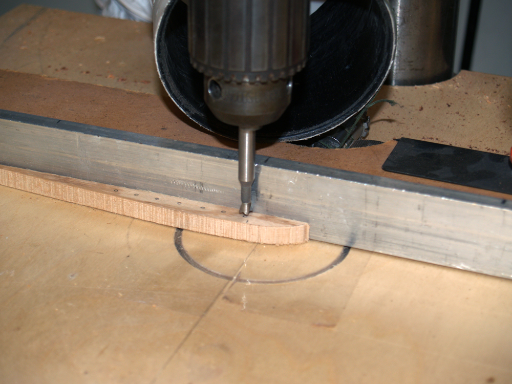
Using the drill press and a variety of Forstner drill bits to create a set of holes in the brace blanks. I am careful to position the holes so that there is a minimal and equal distance to the bottom of the brace for each hole. The distance between each hole is set to provide an interhole pillar that is sufficiently strong but not over built. The hole idea is to create a sufficiently strong brace that has a minimal mass.
 ( 134 ) 24-Jan-2011
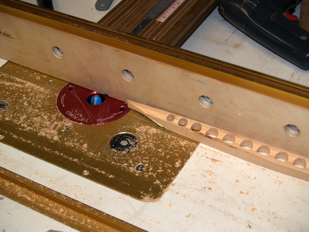
Here we can see the set of holes in a tone bar brace.
 ( 135 ) 24-Jan-2011
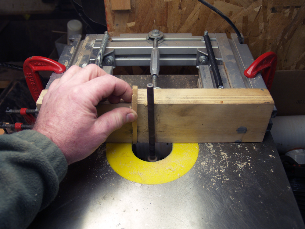
After the holes have been drilled I use the router table to route out a channel along the length of each brace blank.
 ( 136 ) 24-Jan-2011
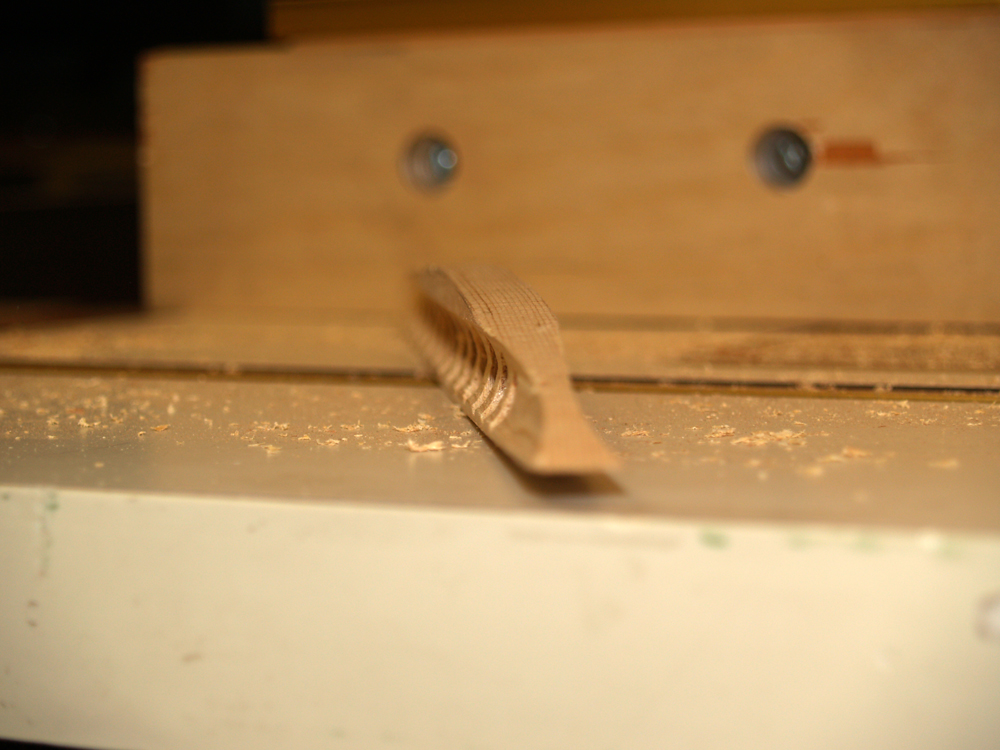
In the end we have a brace cross section that looks like an I-beam. The configuration puts the maximum amount of material at the maximum distance from the neutral axis of the beam. That is a bunch of mechanical engineering speak for the brace will be light and strong. This is a common configuration of structural beams in construction; look at the beams on a bridge or in a building under construction for some examples. Aeronautical engineers extensively use this technique when building an aeroplane; they really wand light and strong.
 ( 137 ) 24-Jan-2011
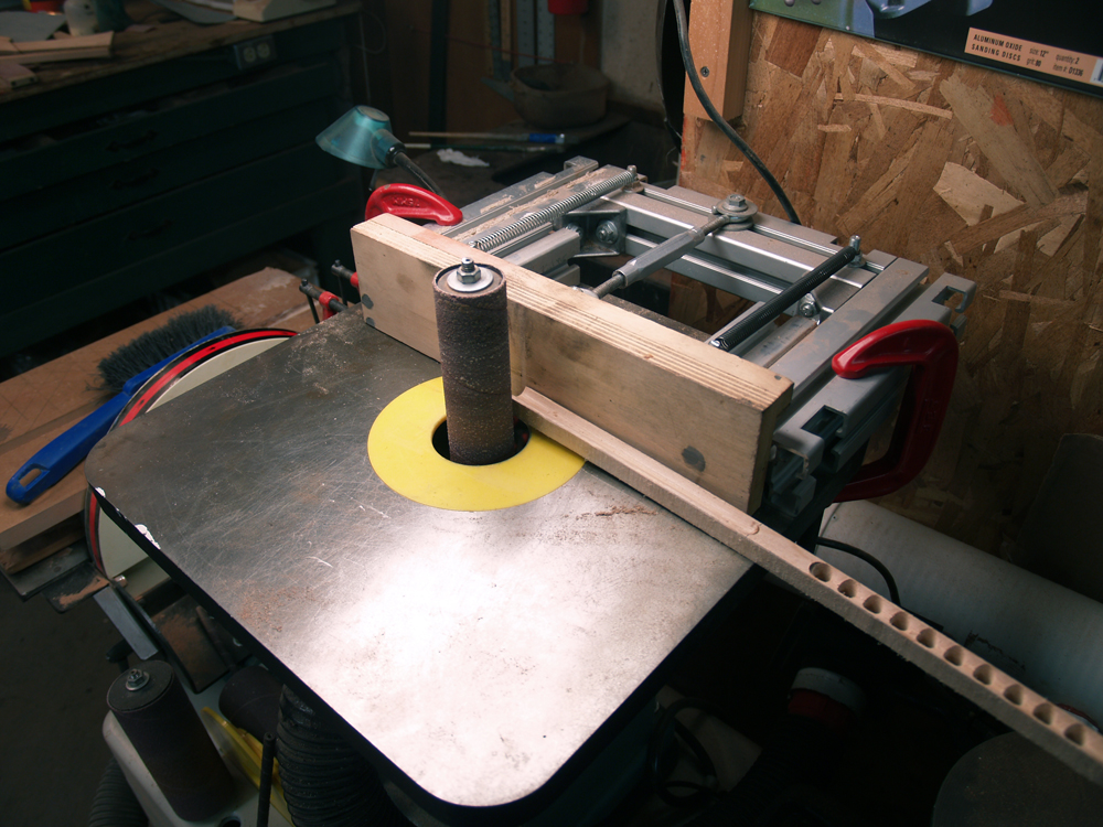
In this picture I am using my oscillating sander to dimension the height of the main x-braces. I want both arms of the main x-brace to have exactly the same height.
 ( 138 ) 24-Jan-2011
And in this picture I am sanding the final shape of the main back brace. When I get ready to install the braces they will be trimmed up for their final fit.
 ( 139 ) 24-Jan-2011
I use the oscillating sander to create the I-beam channel in the finger braces. These braces are too small to use the router for this job.
 ( 140 ) 24-Jan-2011
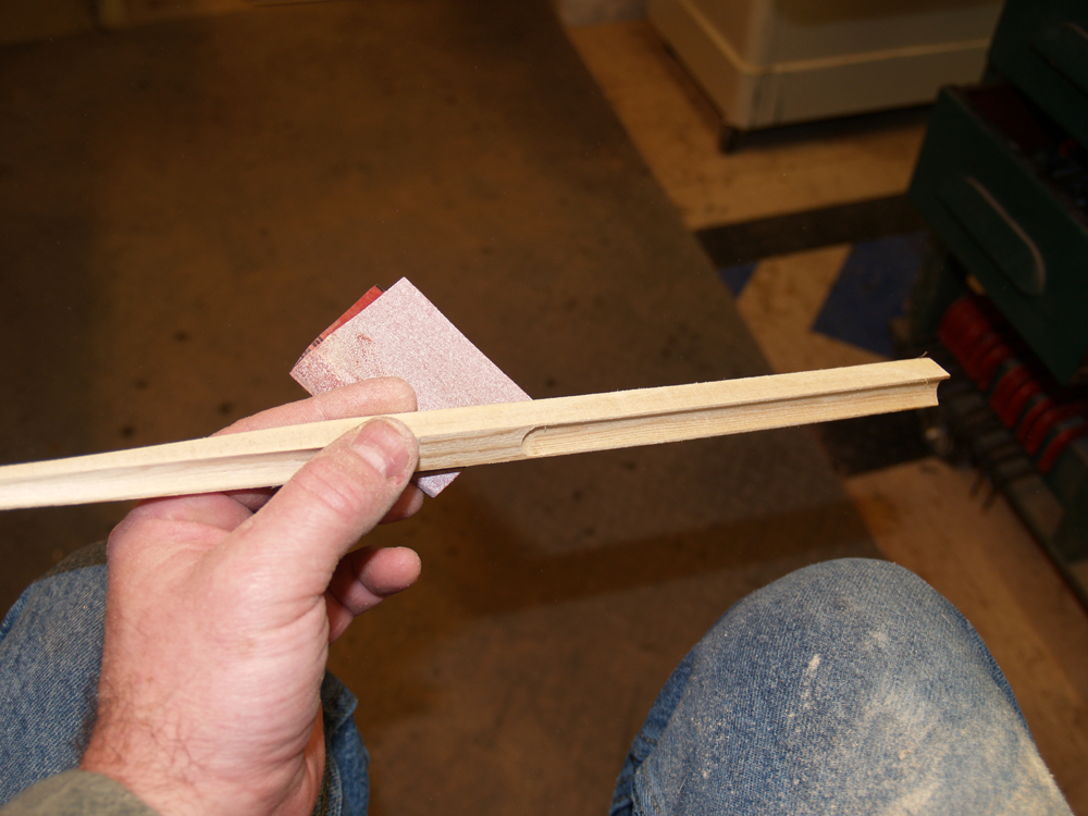
After the braces have there final shape a little hand sanding finishes the job.
 ( 141 ) 24-Jan-2011
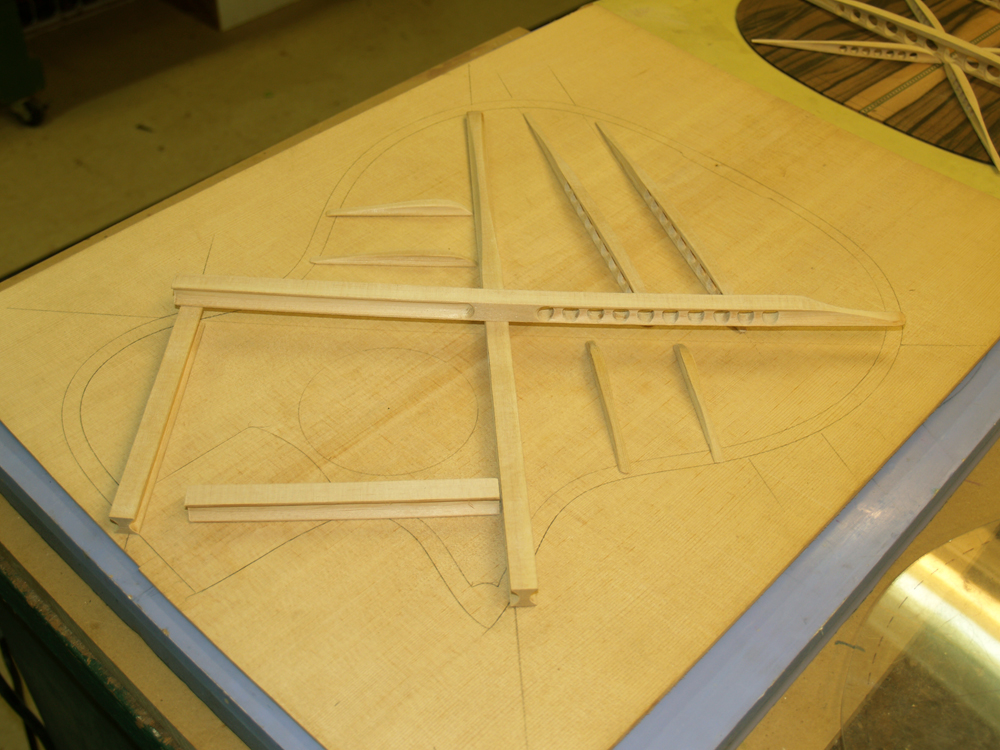
Here I have laid out the back braces on the back plate.
 ( 142 ) 24-Jan-2011
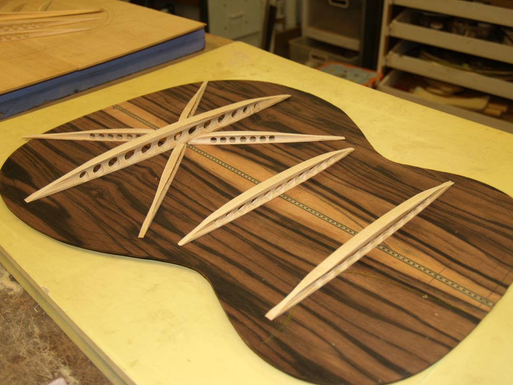
And here I have laid out the top braces.
 ( 143 ) 24-Jan-2011
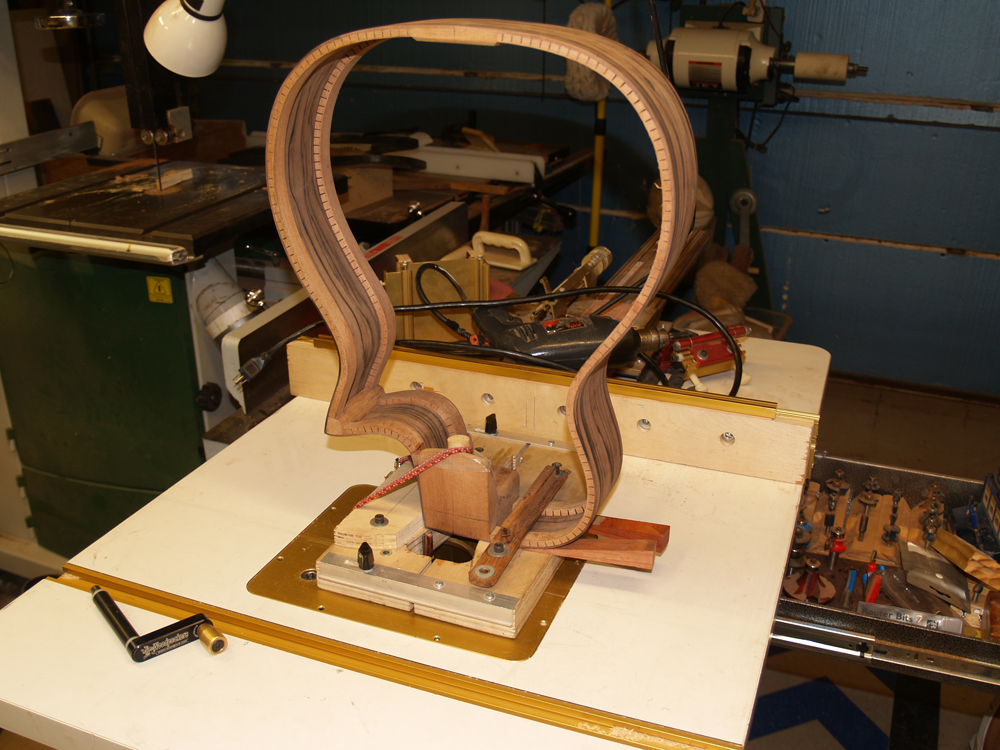
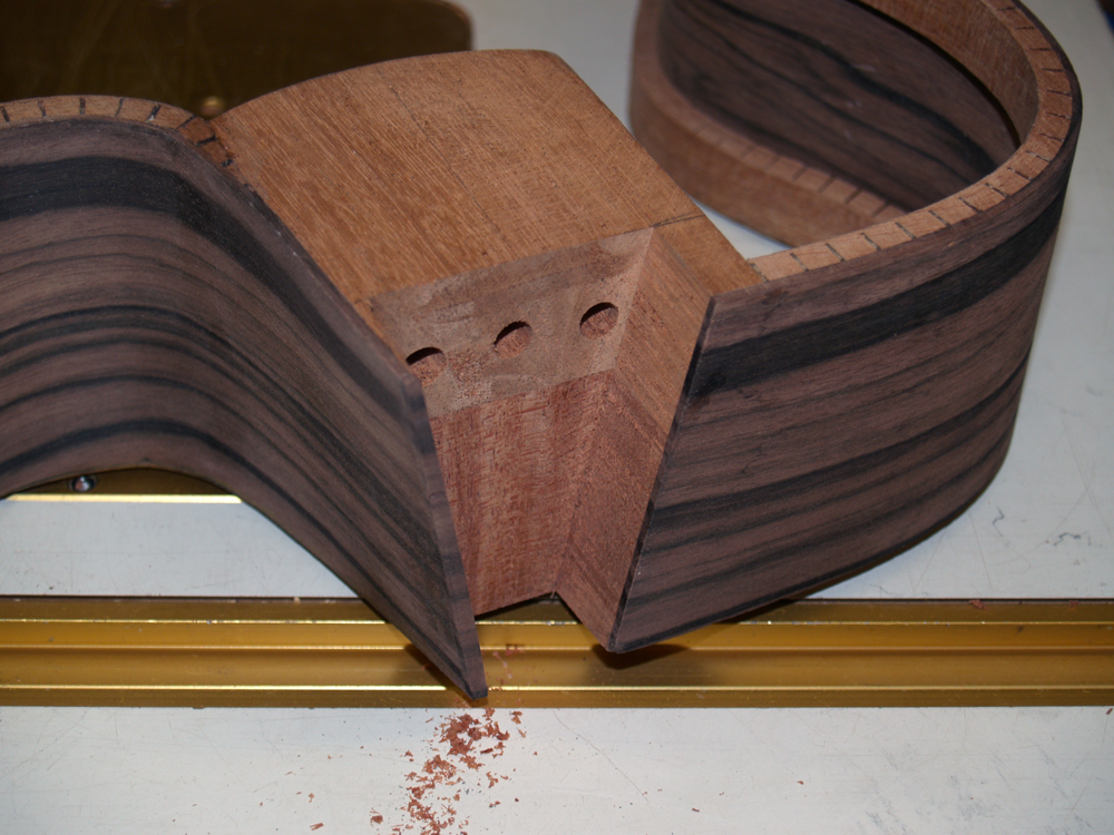
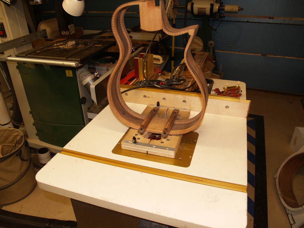
One of the unique features of a Portland Guitar is the User Adjustable Tilt Action Neck. In this picture I have mounted the side rim in a special fixture that will allow me to accurately route out the heel channel.
 ( 144 ) 24-Jan-2011
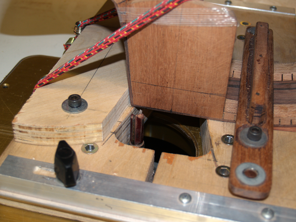
This fixture has a template that has the same shape as the heel of the neck. A special router bit follows this shape and I can control the depth of the cut. I spend a significant amount of time making sure that everything is lined up just right before I start this bit.
 ( 145 ) 24-Jan-2011
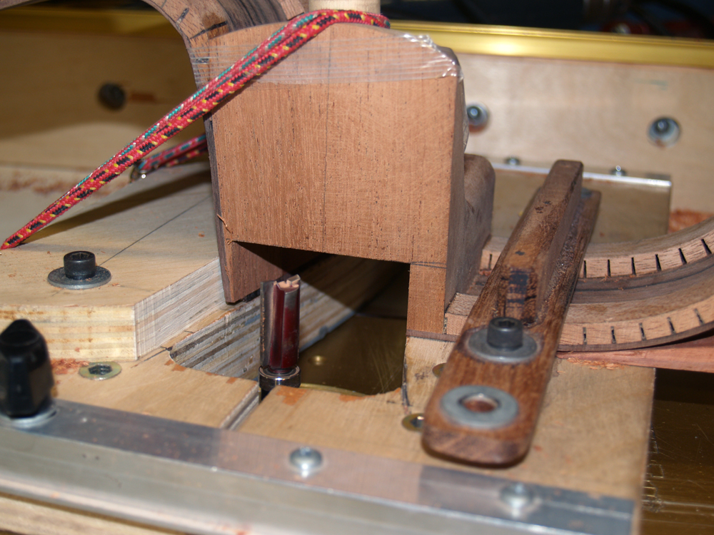
Here you can see the the router bit in the channel it is creating.
 ( 146 ) 24-Jan-2011
And finally the completed channel. This channel will house the hardware that makes the adjustable neck possible. More on this later.
 ( 147 ) 24-Jan-2011
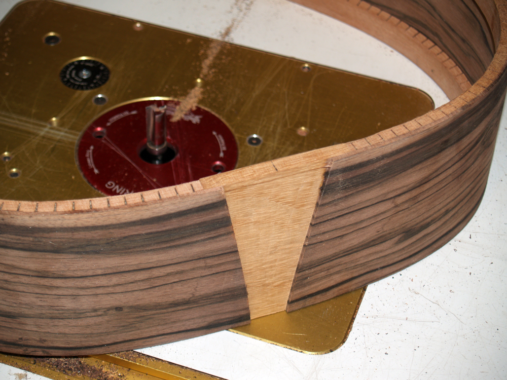
I use the same fixture to route out a channel for the tail graft.
 ( 148 ) 24-Jan-2011
I will install a tail graft into this channel that will compliment the rosettes and the headstock.
 ( 149 ) 24-Jan-2011
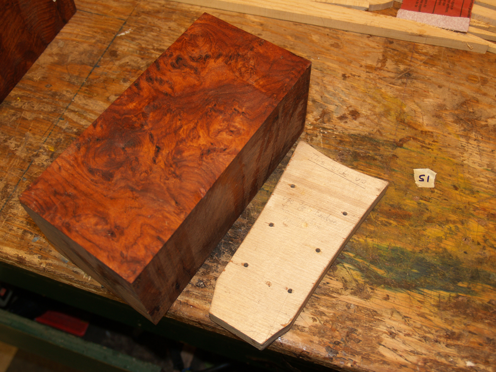
This guitar will use Amboyna burl and Brazilian rosewood for the appointments. Here I have a block of Amboyna burl that I am going to cut some veneer slices from.
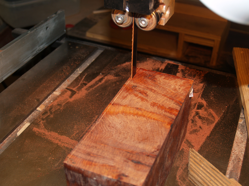 ( 150 ) 24-Jan-2011
I have set up the band saw to cut the veneers.
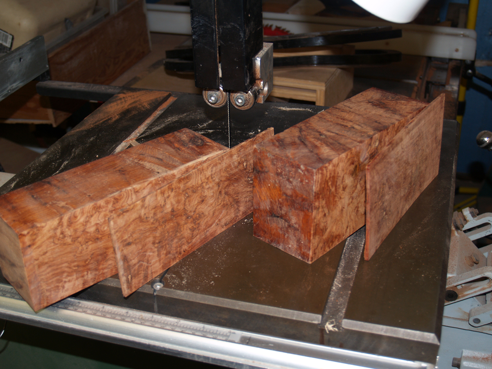 ( 151 ) 24-Jan-2011
And here are two slices from the Amboyna burl blocks.