 |
(51) 3-April-2010
In
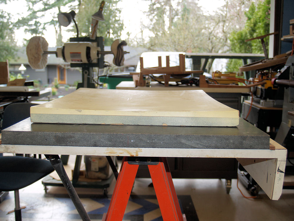
this picture is the dish that I use to define the shape of the back
side of the guitar. I have a similar dish that is used for
the
top. |
 |
(52) 3-April-2010
In
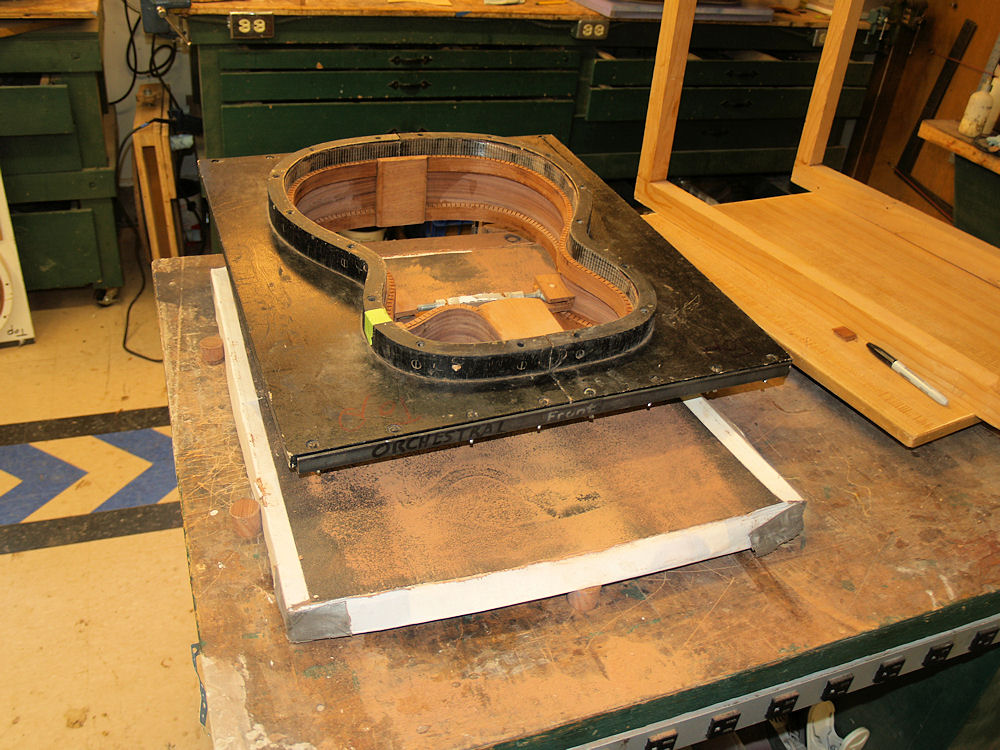
this picture I am using the dish with a sheet of sandpaper over it to
sand
the edges of the rim to conform to the shape of the dish. I
place
the rim of the guitar in its form and then sand the rim down until it
makes good contact all of the way around the edge. This
ensures
that when I glue the back onto the rim a solid joint will be made. |
 |
(53) 3-April-2010
I
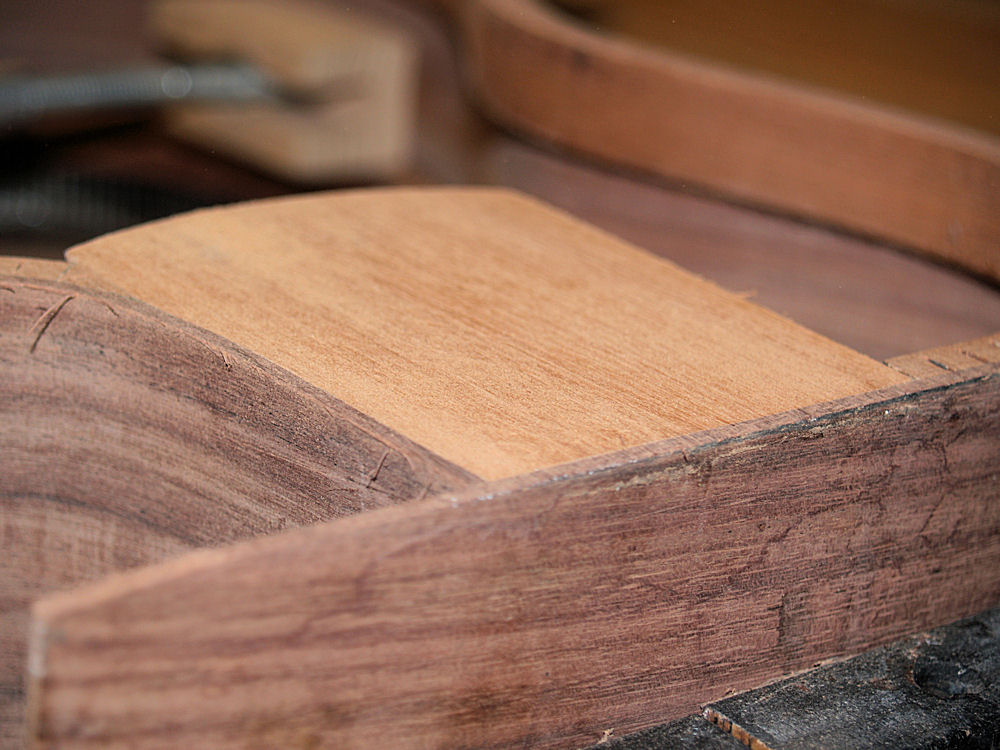
do the same thing for the top edge of the rim using the top dish.
This picture
shows a close up of the heel block after it has been sanded to shape. |
 |
(54) 3-April-2010
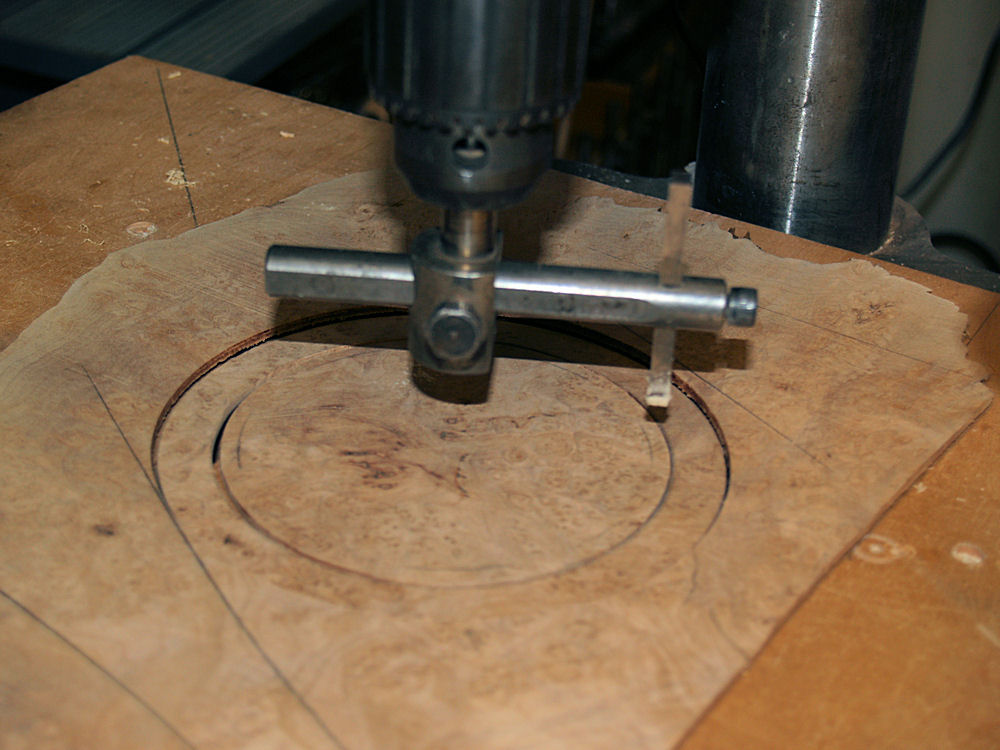
In this picture I am using a circle cutting tool to cut the center
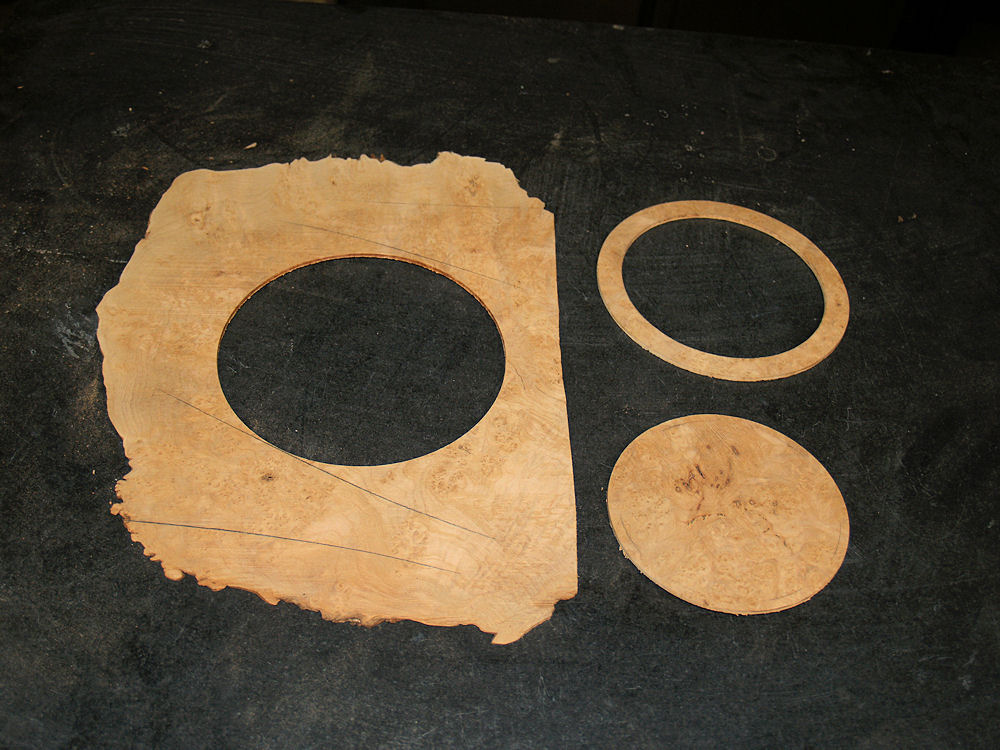
piece of the rosette out of a burled maple blank. |
 |
(55) 3-April-2010
I
will use the circle in the upper right for the rosette, the solid
circle will be used to create a frame for the contra-rosette, and the
remainder of the blank will be used for the tail graft and the heal
cap. The head stock veneer will be made out of a similar
piece of
burled maple. This set of appointments will give the guitar a
sense of consistency from the tail to the head. |
 |
(56) 3-April-2010
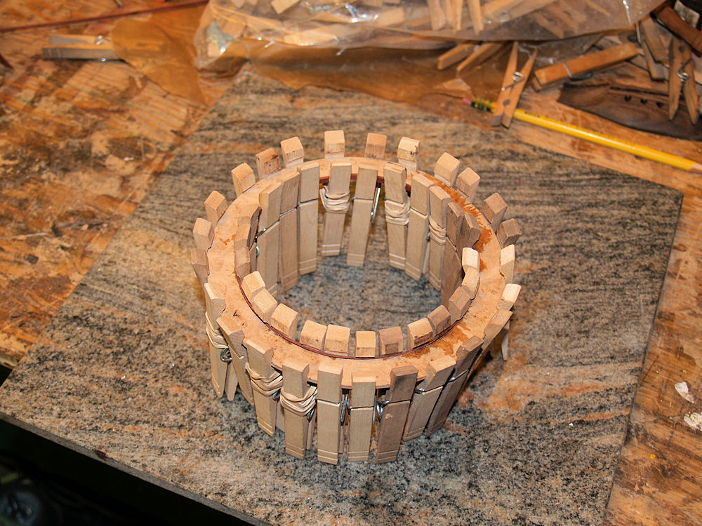
Here I am gluing the trim pieces onto the rosette. |
 |
(57) 3-April-2010
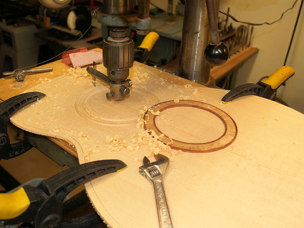
I use my circle cutter again to route out a channel for the rosette. |
 |
(58) 3-April-2010
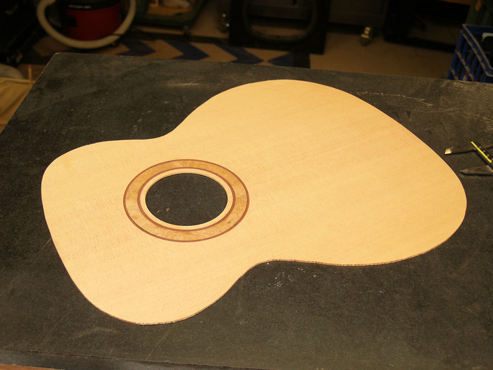
I glue the rosette into the channel leaving it a little bit proud of
the top surface. |
 |
(59) 3-April-2010
And
then the drum sander is used to sand everything flush and and to
dimension the top thickness to about 100 mils. The top
thickness
will be reduced to between 75 mils to 90 mils during subsequent
processes. The edges will be reduced more than the center to
to
allow the top to vibrate more freely. |
 |
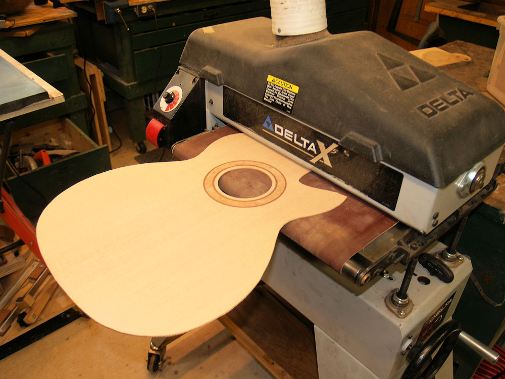
(60) 3-April-2010
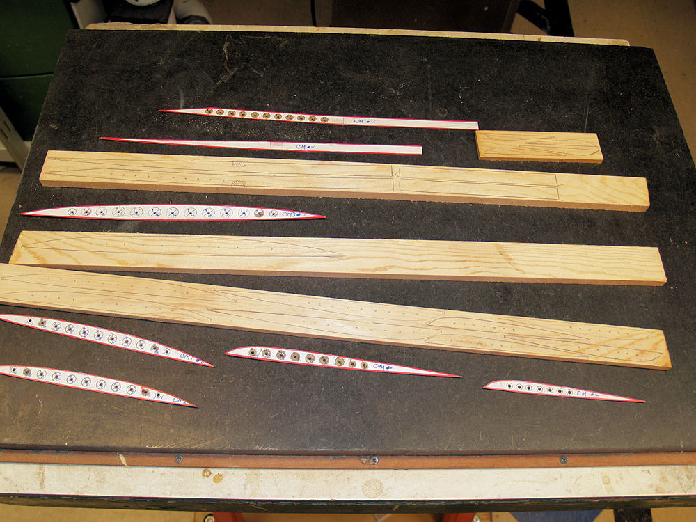
Now I turn my attention to making the braces. I have a set of
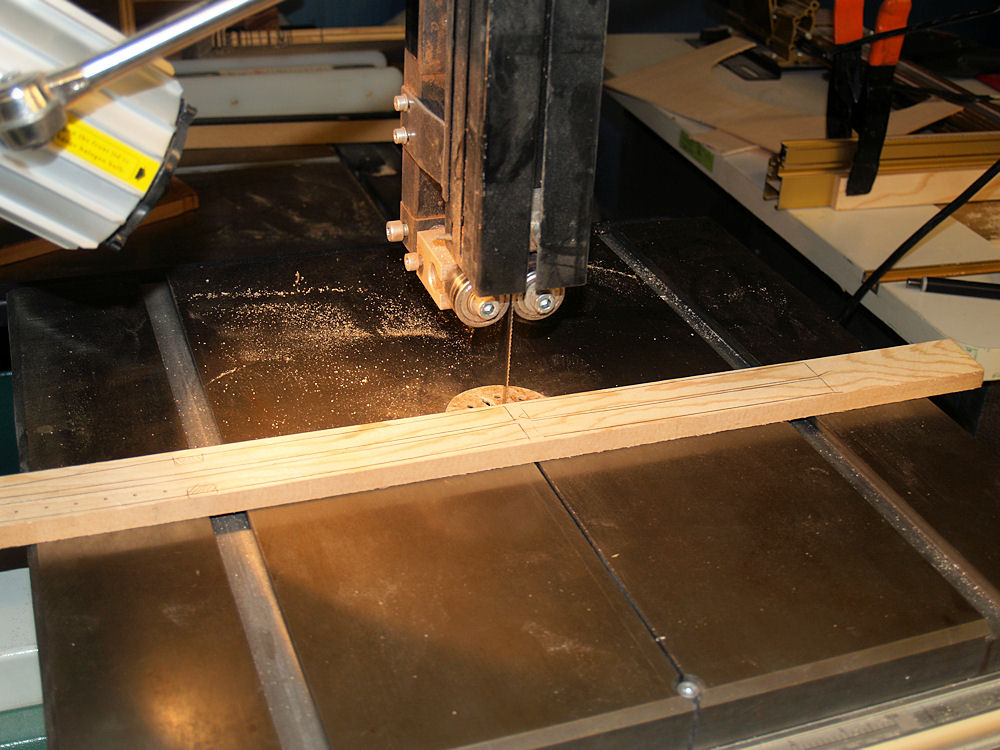
templates that get me started. |
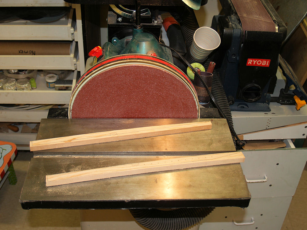
 |
(61) 3-April-2010
Cutting out the braces. |
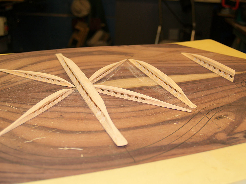
 |
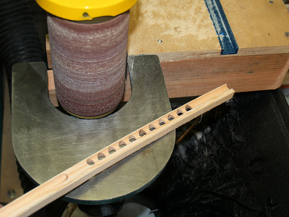
(62) 3-April-2010
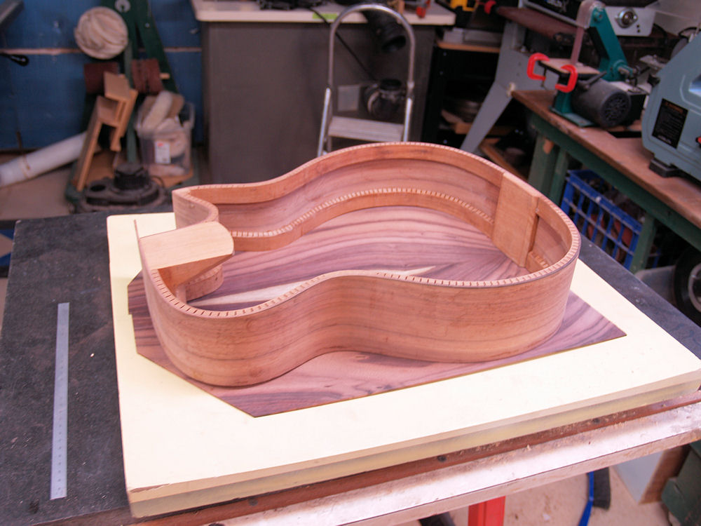
And roughing out the shape. |
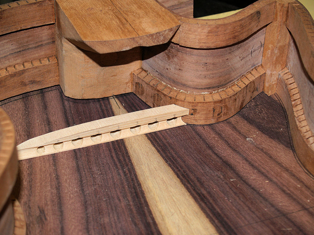
 |
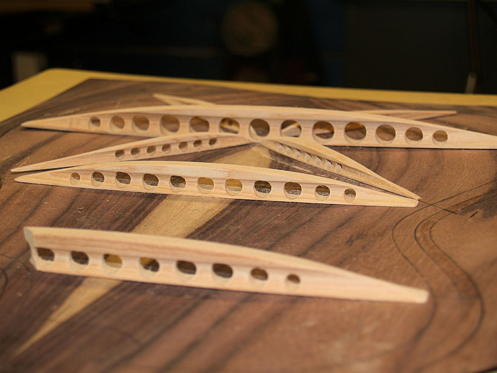
(63) 3-April-2010
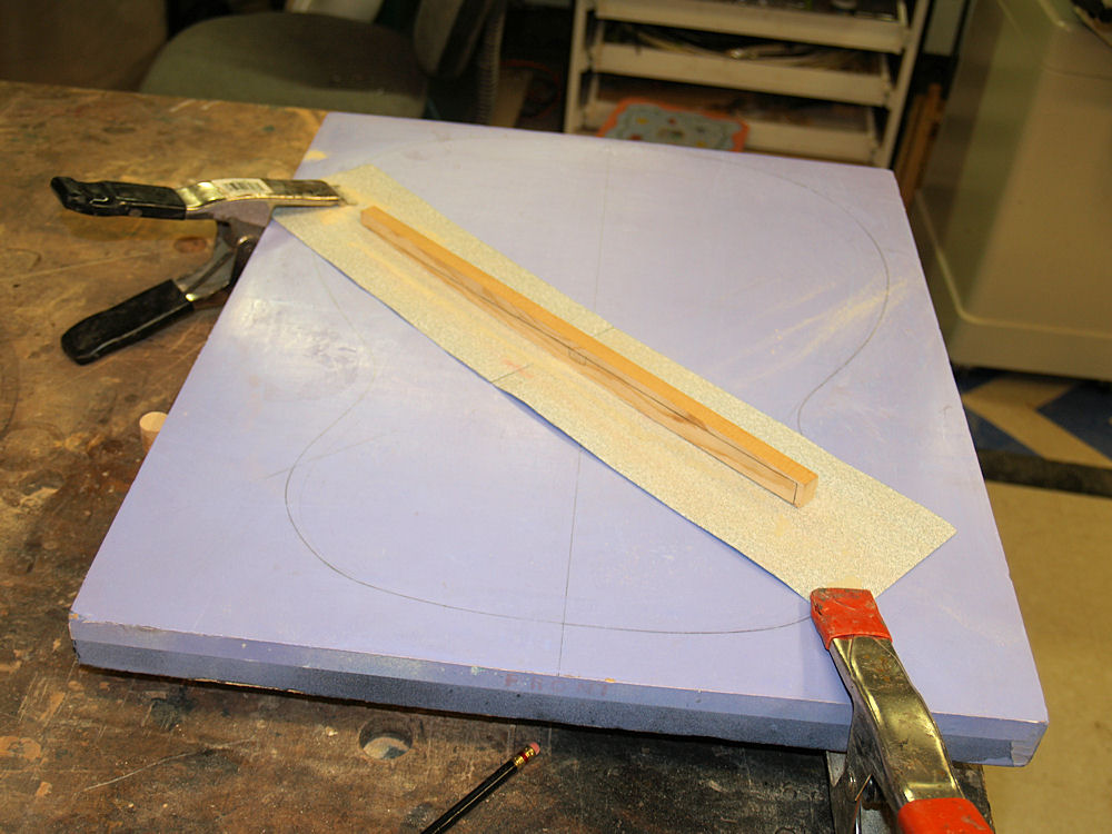
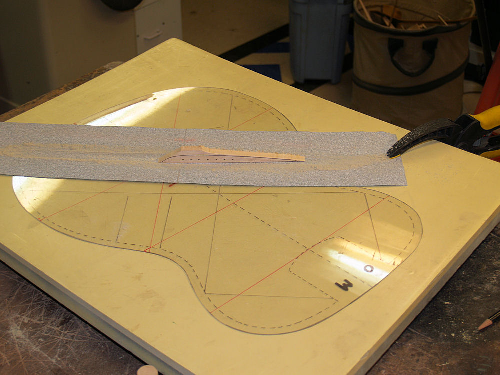
I
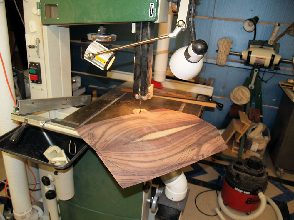
use the top dish to sand the bottom of the braces to shape.
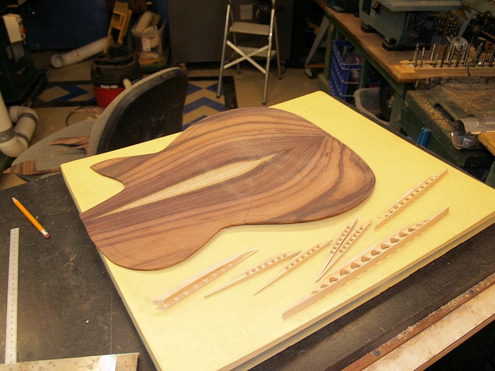
If I am careful the braces will make a perfect fit
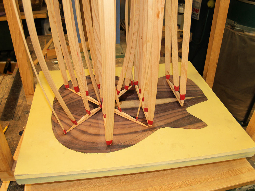
to the
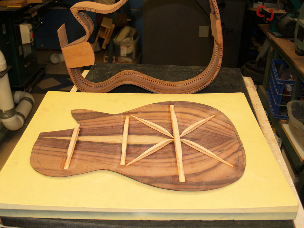
dish. I work the brace blanks until there are no gaps between
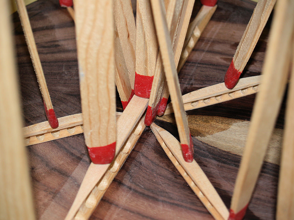
the
braces and the dish. This is very important in that this will
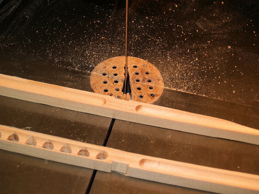
define the shape of the top and ultimately the sound of the guitar.
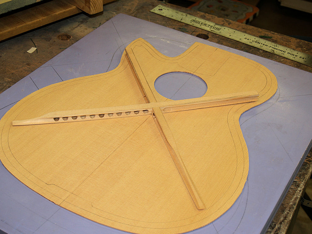
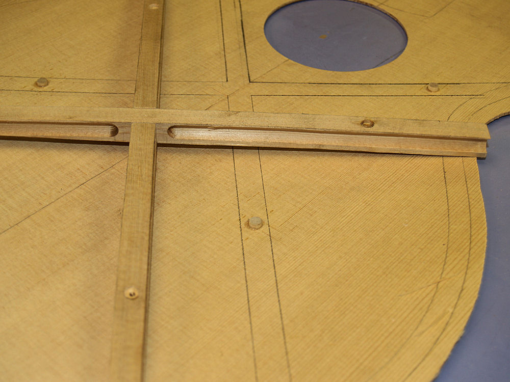
|
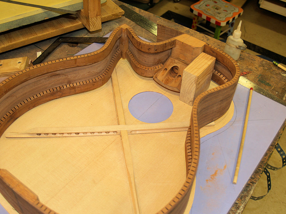
 |
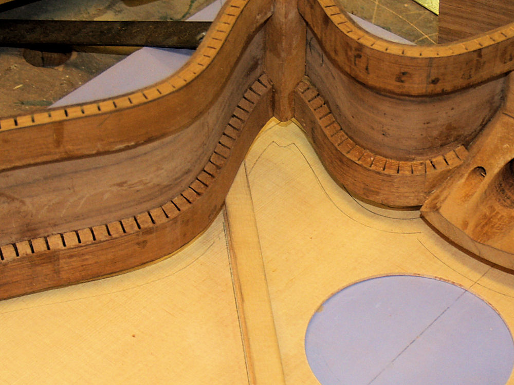
(64) 3-April-2010
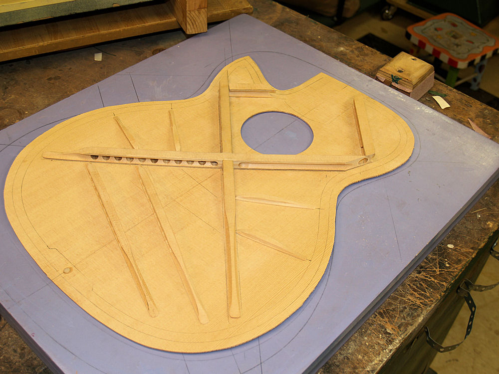
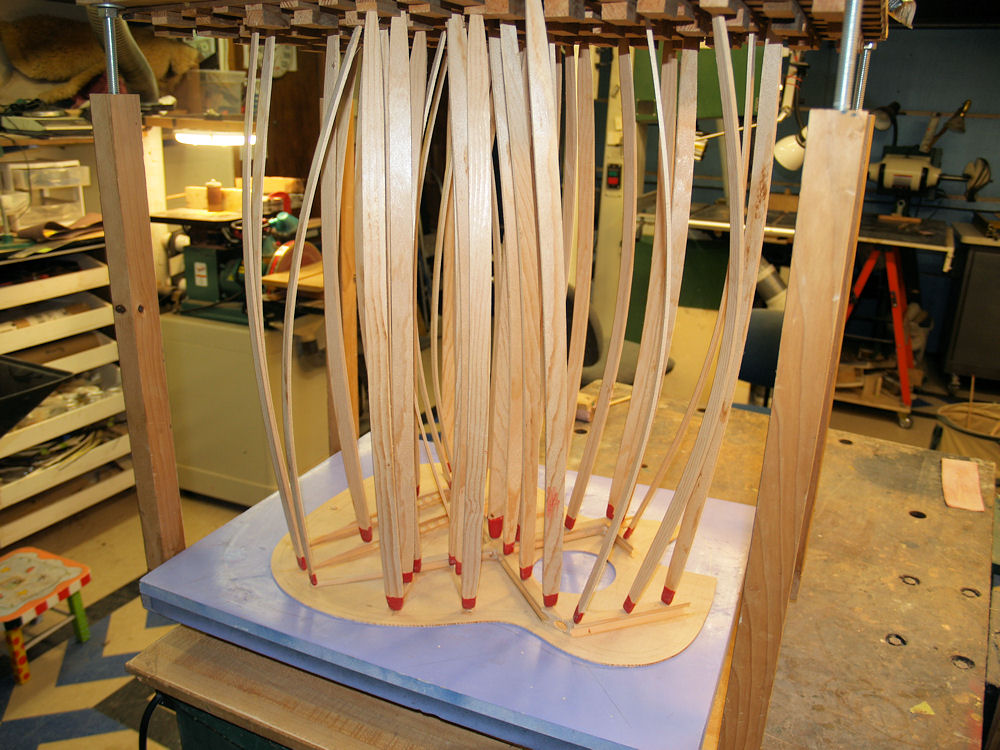
I use the back side dish to make the back braces. |
 |
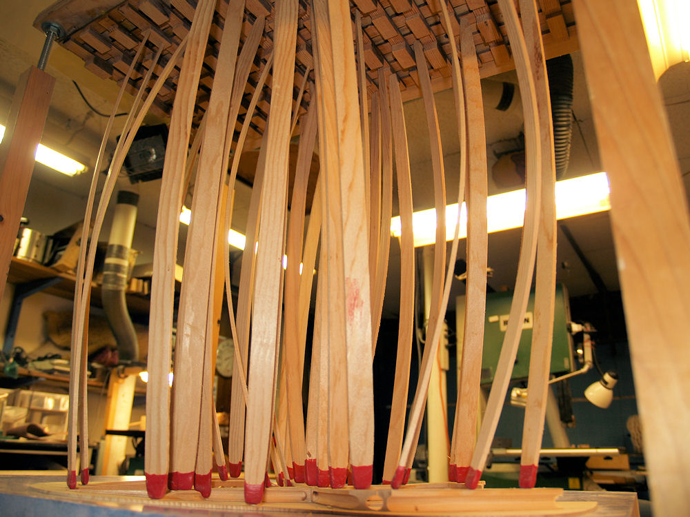
(65) 3-April-2010
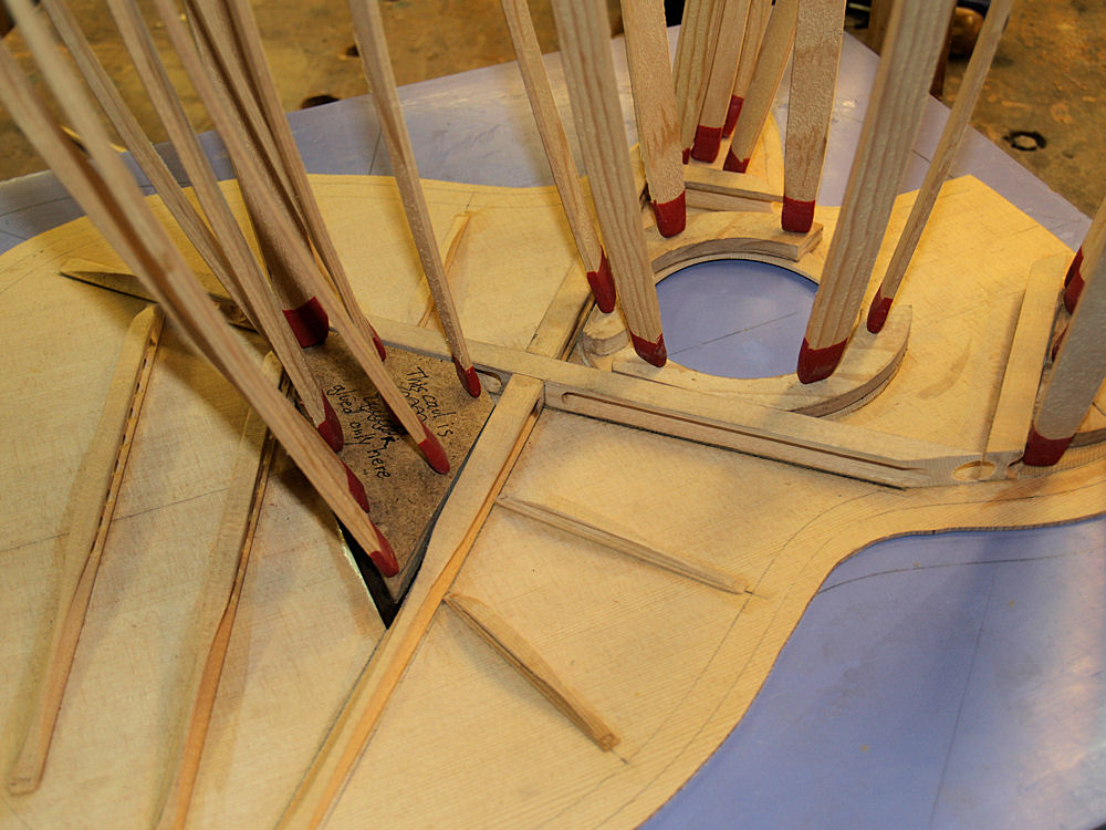
I
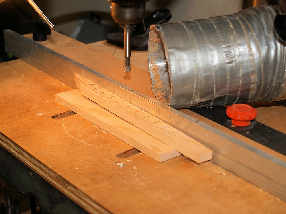
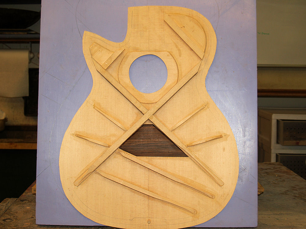
this picture I am drilling the holes that will reduce the mass of the
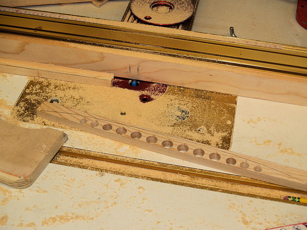
braces. I make what I call engineered braces, or more
humorously
'cool aircraft braces'. These braces are largely responsible
for
the sound quality of the guitar. |
 |
(66) 3-April-2010
After the holes are drilled, I use the router table to route out the
side channels that result in an I-beam construct. |
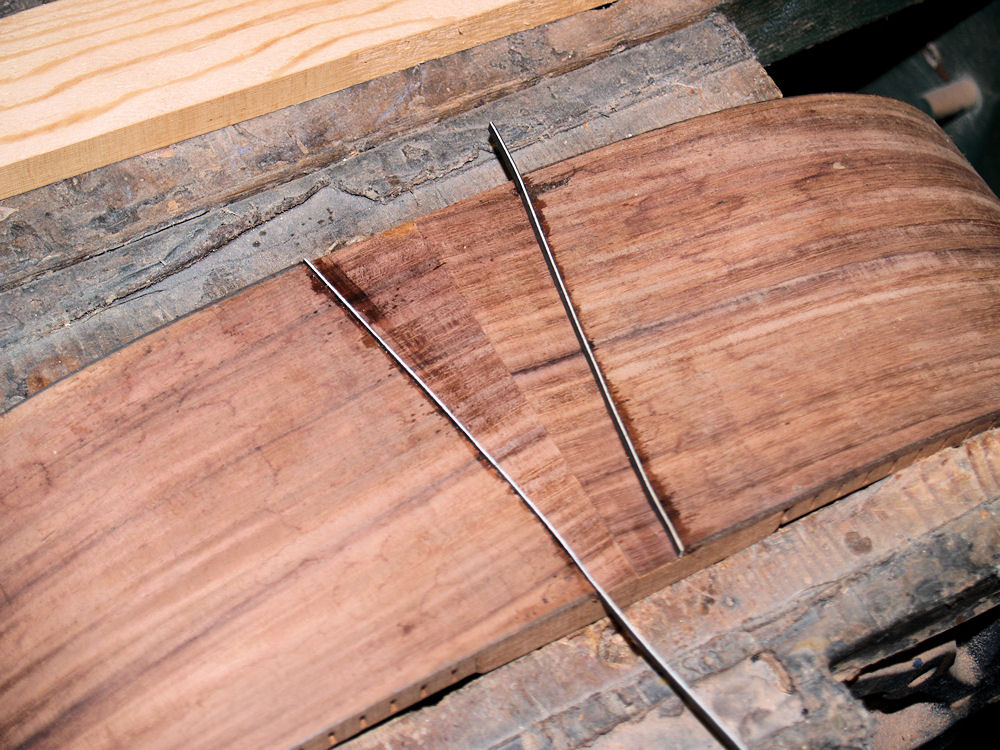
 |
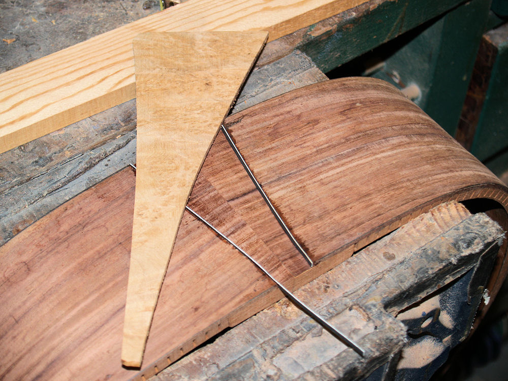
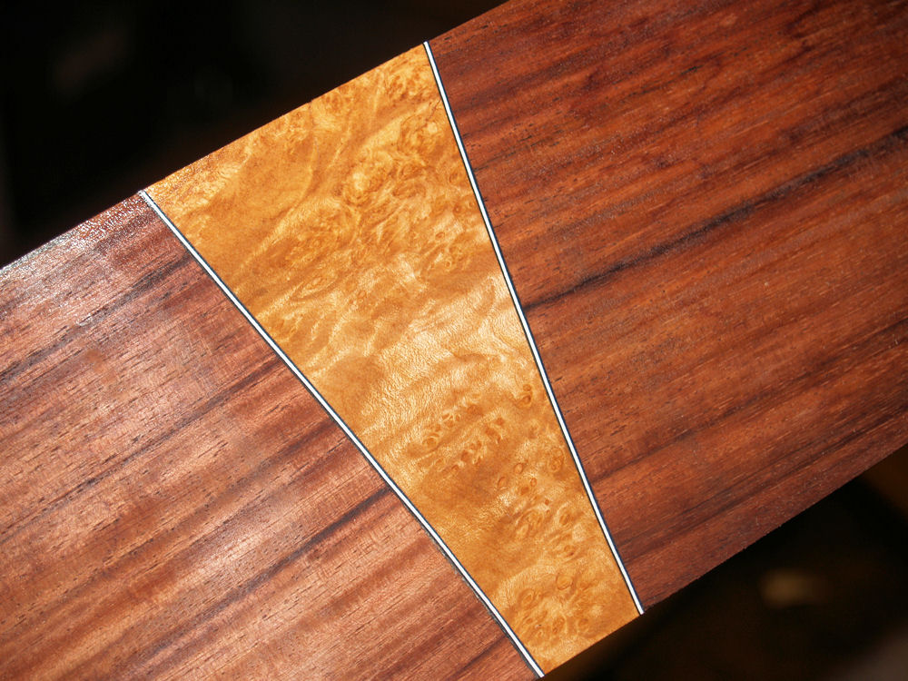
(67) 3-April-2010
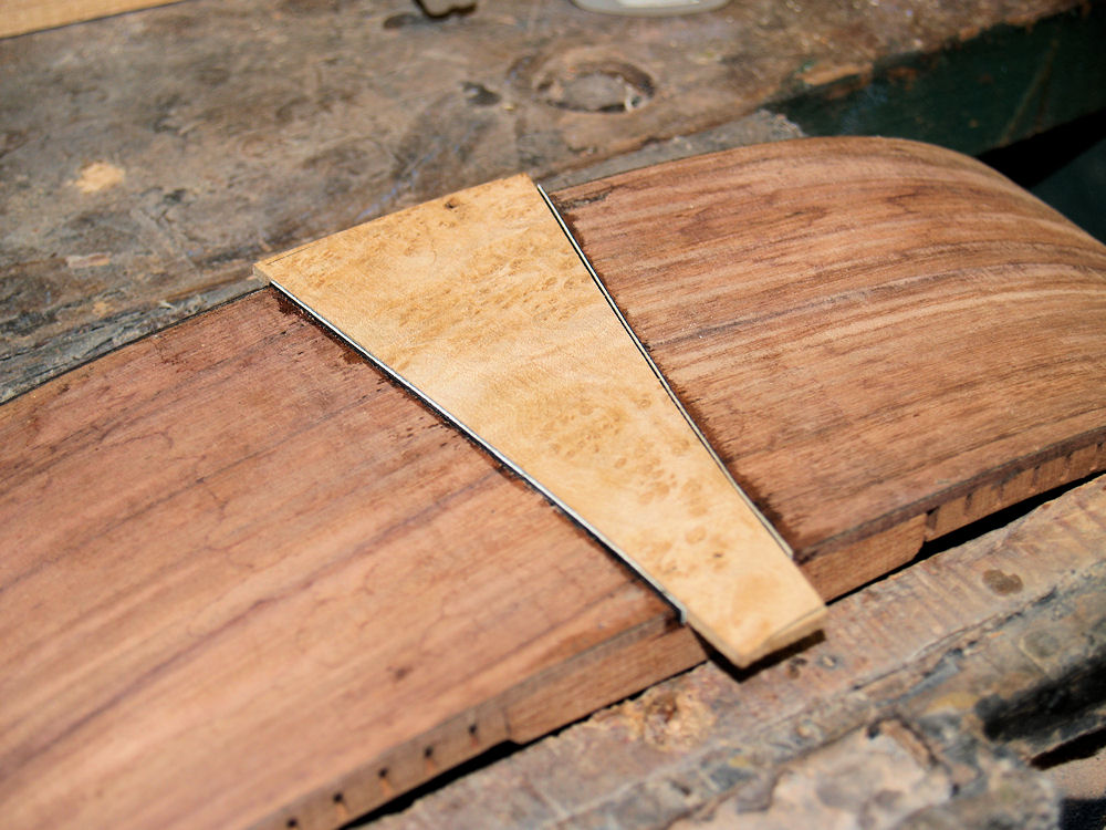
After
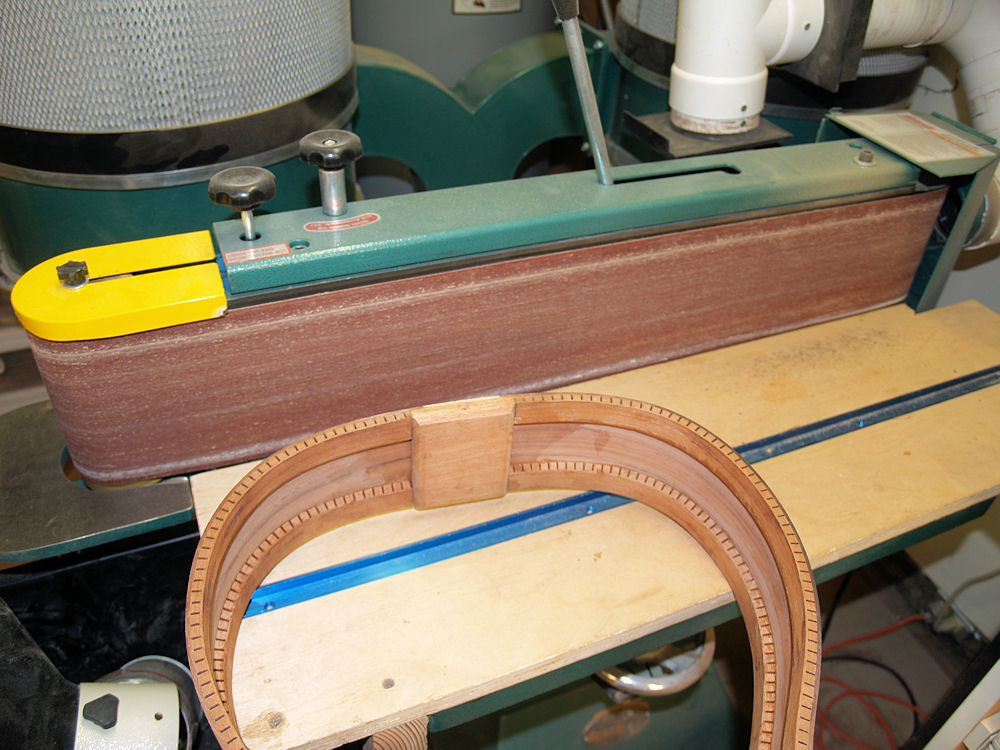
the bottom and sides are defined, I can than trim the top side of the
braces. The result is a very light yet stiff brace.
This
design can produce a brace that is on the order of 40% lighter than a
traditional brace of similar stiffness. |
 |
(68) 3-April-2010
Here I am drawing the outline of the guitar onto the back. |
 |
(69)
3-April-2010
I have to trim this back side brace to fit the cutaway portion of the
guitar.
|
 |
(70) 3-April-2010
Here we see the finished set of back braces. |
 |
(71)
3-April-2010
Another view of the back side braces. |
 |
(72) 3-April-2010
Once I am satisfied with the layout, I cut out the back. |
 |
(73) 3-April-2010
A picture of the back pieces before they are assembled. |
 |
(74) 3-April-2010
I use my go-box to glue the braces into place. |
 |
(75) 3-April-2010
A close up of the go-sticks and braces. |
 |
(76) 3-April-2010
After the glue is dry I take the back out of the go-box and I can tap
it to get a sense of its resonance properties. |
 |
(77) 3-April-2010
In this picture I am cutting the cross channels out of the main
X-braces. I like to make this a very snug fit. |
 |
(78) 3-April-2010
Laying out the main X-brace on the top. |
 |
(79) 3-April-2010
As
I put the top together it is important that I can repeatedly return the
braces to their proper place. I use a set of fiducial buttons
to
define where the braces will go. |
 |
(80) 3-April-2010
With the main X-braces in place I lay the rim over them. |
 |
(81) 3-April-2010
And
I carefully mark the forward leg of braces so when they are trimmed
they will make a tight joint with the rim. The force and
torque
generated by the string tension is transfered through these braces
into the rim and ultimately back to the neck. A good joint in
important to insure that forces are transfered to the rim and don't end
up in the top. |
 |
(82) 3-April-2010
The braces trimmed and ready to be glued in place. |
 |
(83) 3-April-2010
I
use the go-box to glue the brace in place. I make sure the
braces
make good contact with the top through out their length, especially at
the tips. |
 |
(84) 3-April-2010
Another view of the go-box in action. |
 |
(85) 3-April-2010
A second round in the go-box glues in the bridge plate, the hole plate,
and the shoulder plates. |
 |
(86) 3-April-2010
All of the top braces in place. |
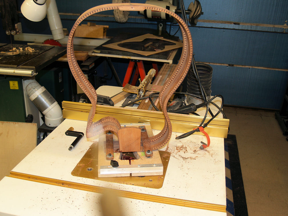 |
(87) 3-April-2010
I use my router table and a special jig to rout out the heal channel
for the neck. |
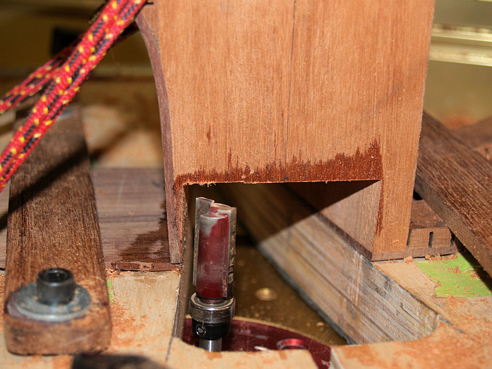 |
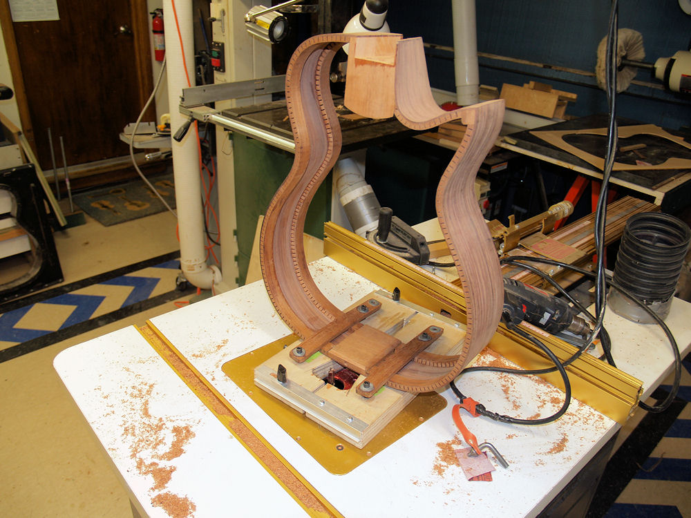
(88) 3-April-2010
A
1 inch deep channel is created to accept the heal of the neck and house
all
of the hardware that makes up the User Adjustable Tilt Action Neck. |
 |
(89) 3-April-2010
I use the same jig to route out a channel for the tail graft. |
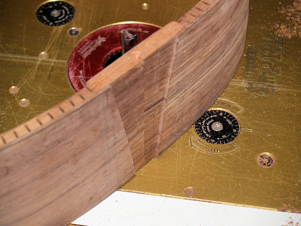 |
(90) 3-April-2010
The tail graft will mirror the shape of the heal. |
 |
(91) 3-April-2010
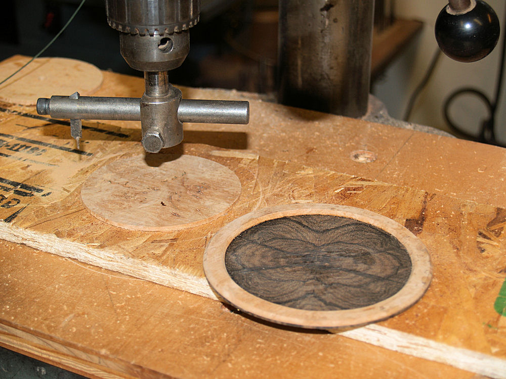
In this picture I am using my circle cutter to cut a frame for the
contra-rosette, made up of a quad matched set of Zircote. |
 |
(92) 3-April-2010
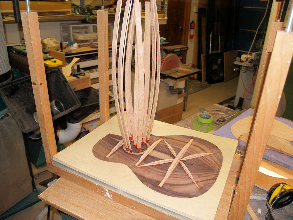
The go-box to glue it in place. |
 |
(93) 3-April-2010
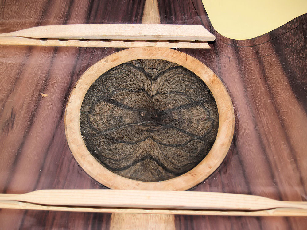
A view of the contra-rosette. |
 |
(94) 3-April-2010
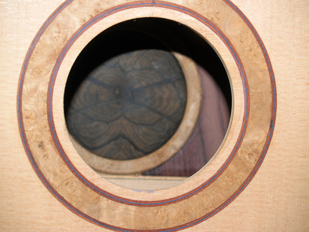
I dry fit the top and back to the rim and took a peek at how the
rosettes will look. |
 |
(95) 3-April-2010
To install the tail graft I first glue in the pinstripes that will
outline the rim. |
 |
(96) 3-April-2010
I cut the tail graft from the burled maple blank and carefully trim it
until it makes a good fit in the channel. |
 |
(97) 3-April-2010
I glue the piece in place leaving it slight proud of the surface. |
 |
(98) 3-April-2010
And after the glue has set I sand it flush with the surface. |
 |
(99) 3-April-2010
I have wet the surface of the tail graft to get an idea of how it will
look when the finish is applied. |