 ( 63 ) 17-Nov-2011
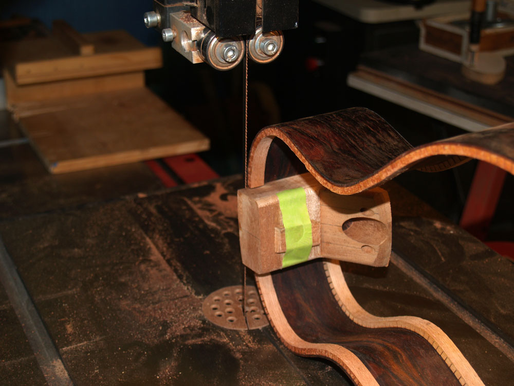
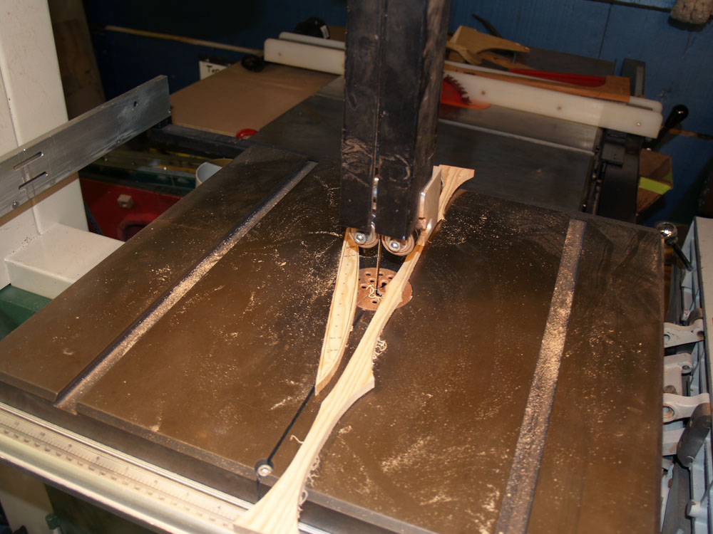
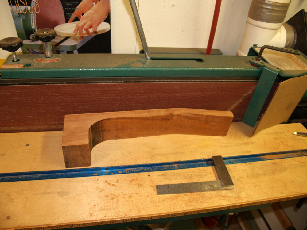
In this picture I am using my bandsaw to trim off the excess from the heal block.
( 63 ) 17-Nov-2011
In this picture I am using my bandsaw to trim off the excess from the heal block.
 ( 64 ) 17-Nov-2011
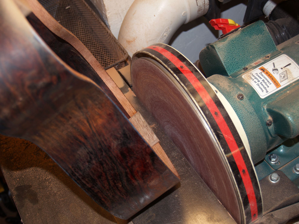
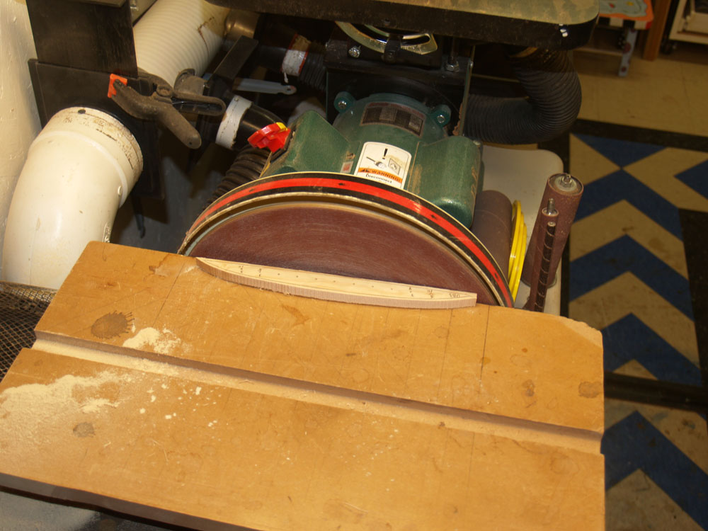
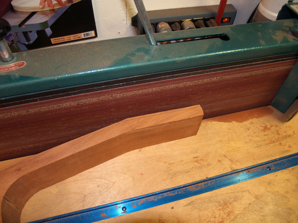
And here I am using the disk sander to trim up the tail block.
 ( 65 ) 17-Nov-2011
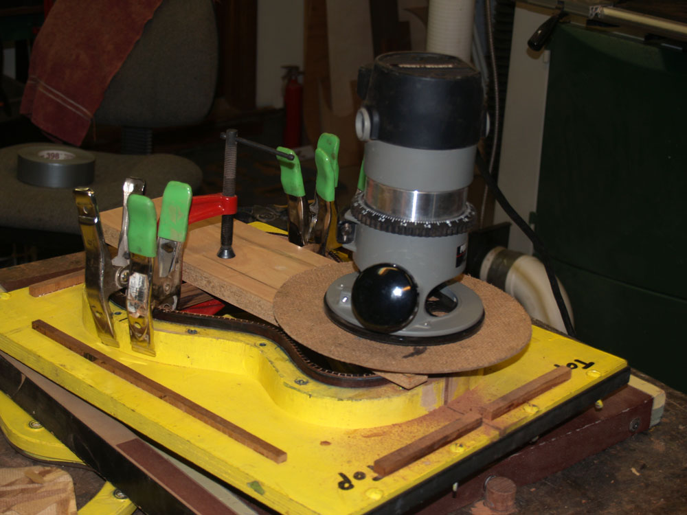
I need to sand the edges of the sides so that they will perfectly match the shape of the top and back. The top and the back are nominally shaped like a bowl with a radius of about 12 to 14 feet. The bowl shape helps to make the top and back stiff and strong while allowing them to be a bit thinner than a flat top. I think the curves make the instrument look better too. I use the top and back forms with sanding sheets to do this. Here I have marked the edge of the rim with a magic marker. When all of the marker is sanded away I know that I have a good match.
 ( 66 ) 17-Nov-2011
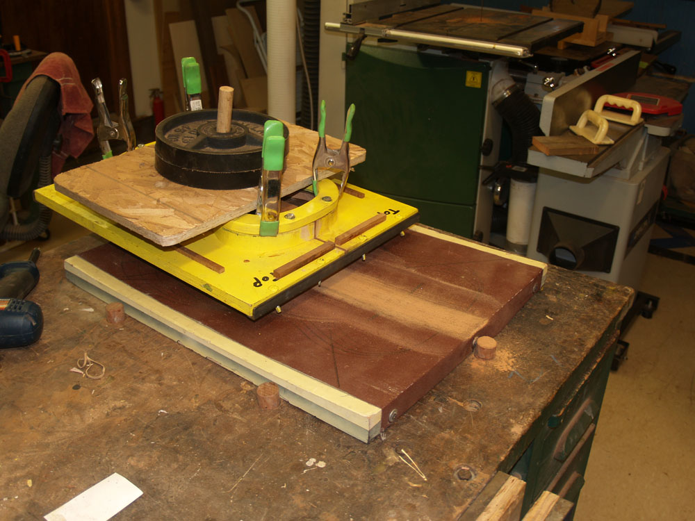
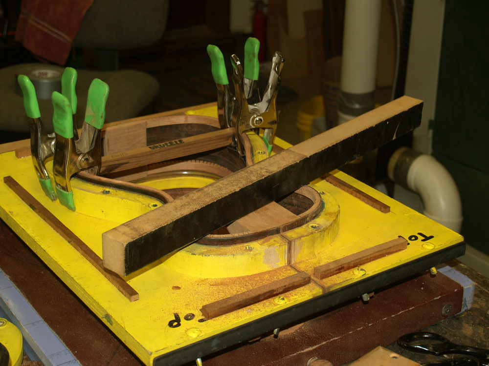
The back form is on the bottom in this picture with a sanding sheet attached to it. I have mounted the sides in its form with the bottom edge standing proud and in contact with the sanding sheet. I put a couple of weights on top to help apply even pressure. Then I push the form back and forth until the marks on the edge are gone. Both the top and back edges get this treatment. A bit of a work out.
 ( 67 ) 17-Nov-2011
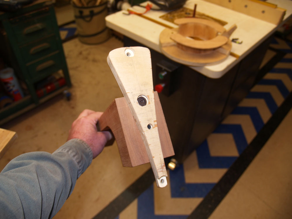
To ensure the top of the heal block has the right shape I trim it up with this router fixture.
 ( 68 ) 17-Nov-2011
And then I round it up with this sanding block.
 ( 69 ) 17-Nov-2011
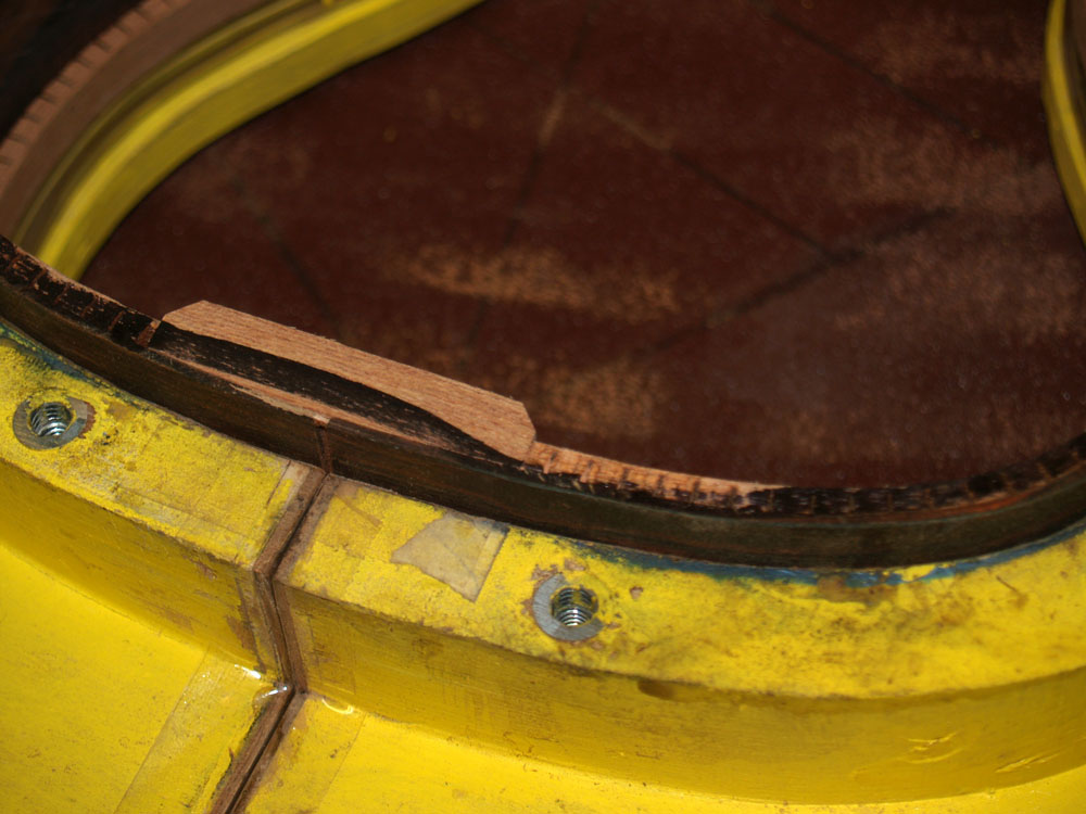
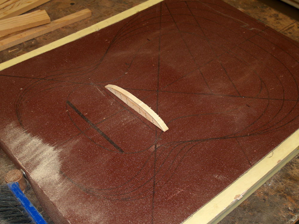
Here I am sanding a bevel into the tail block to match the width of the kerfing. It also looks better, even though no one will ever see it. I'll know it is there though.
 ( 70 ) 17-Nov-2011
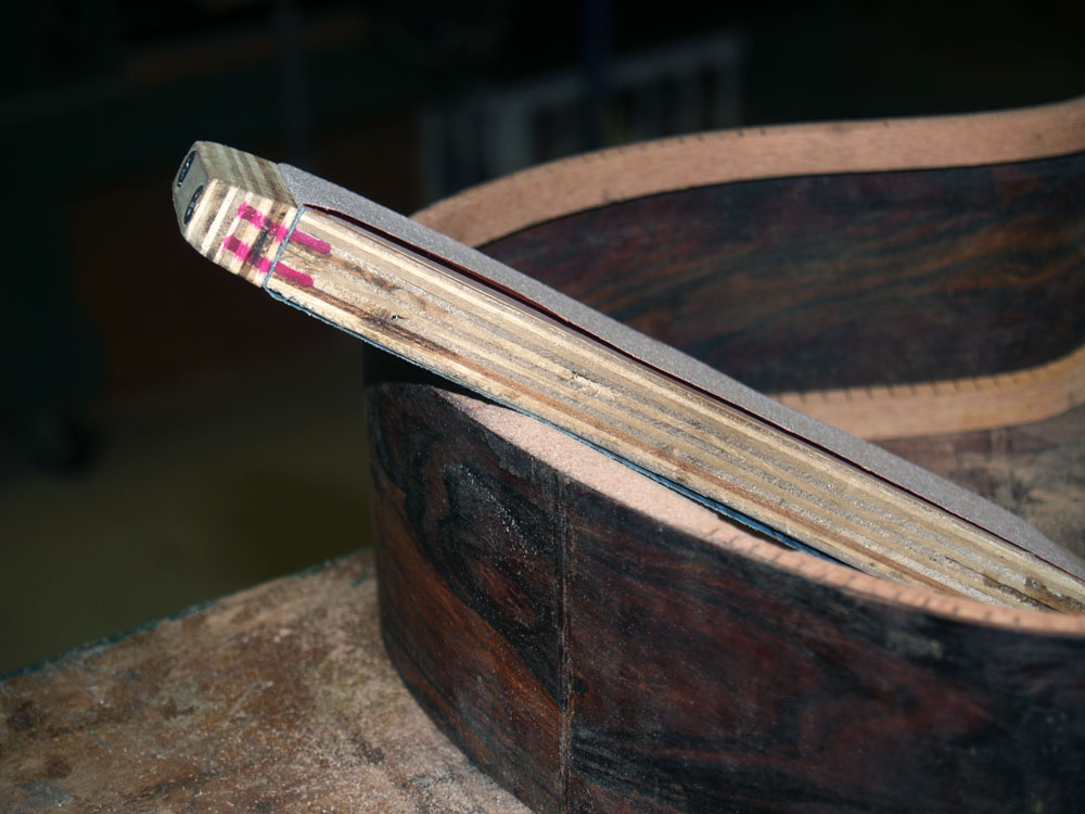
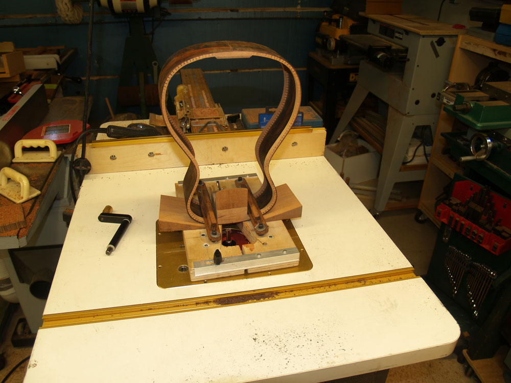
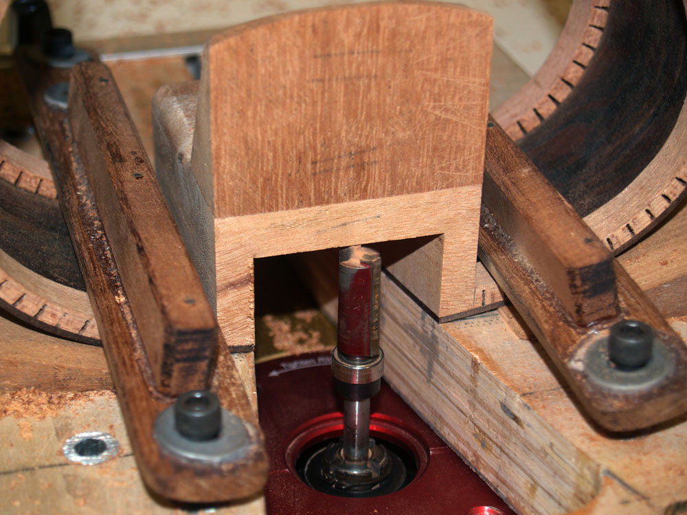
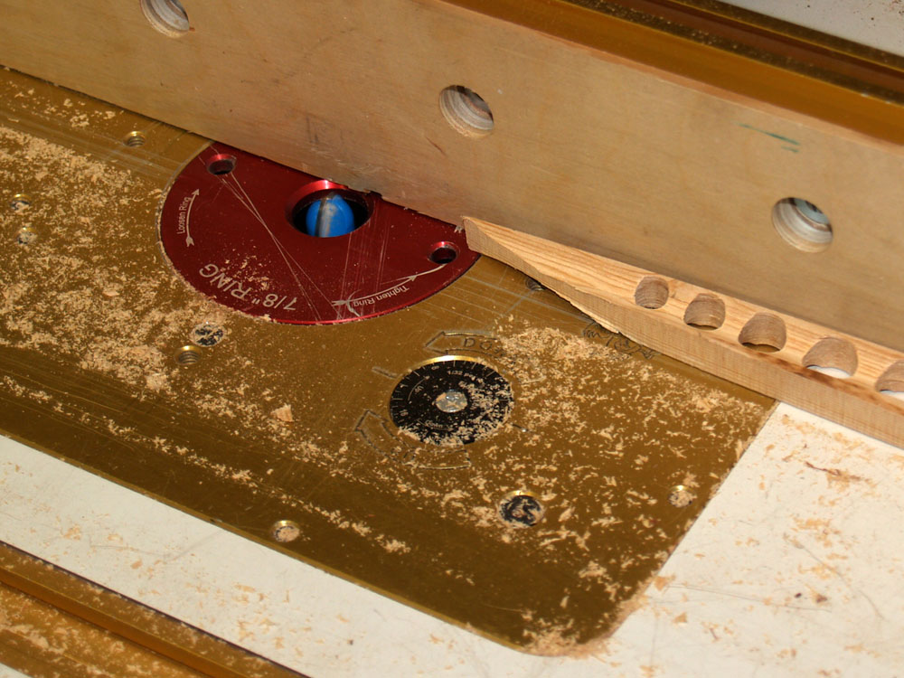
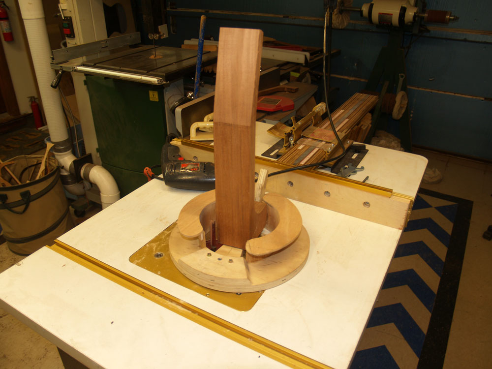
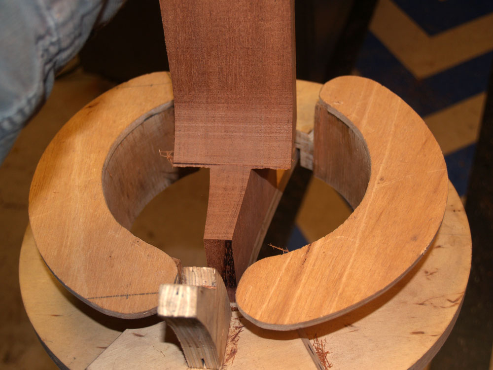
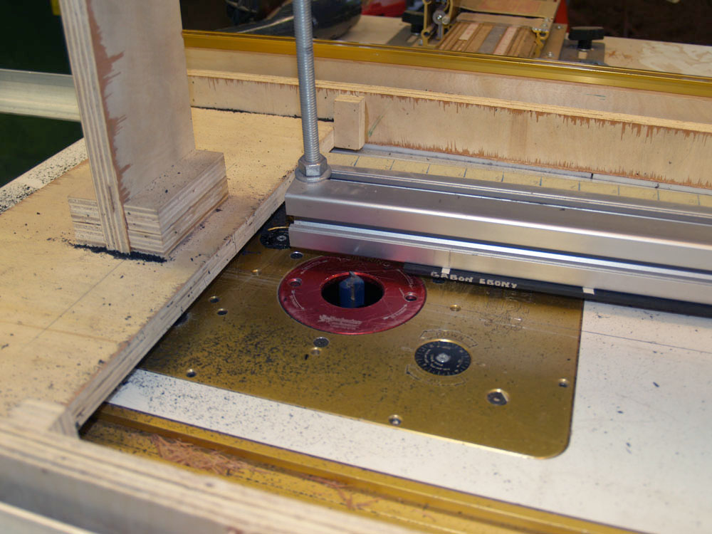
In this picture I have mounted the the side assembly (sometimes called the rim) into this routing fixture that will guide the creation of the heal channel. The heal channel will house the neck adjustment hardware.
 ( 71 ) 17-Nov-2011
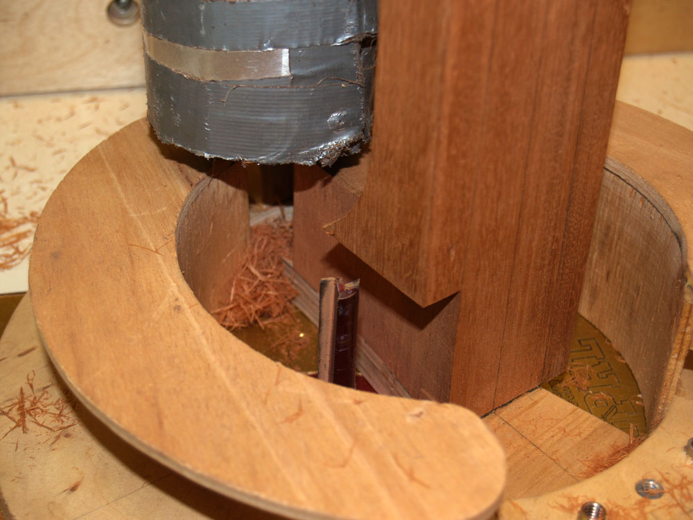
Here you can see the top of the heal channel.
 ( 72 ) 17-Nov-2011
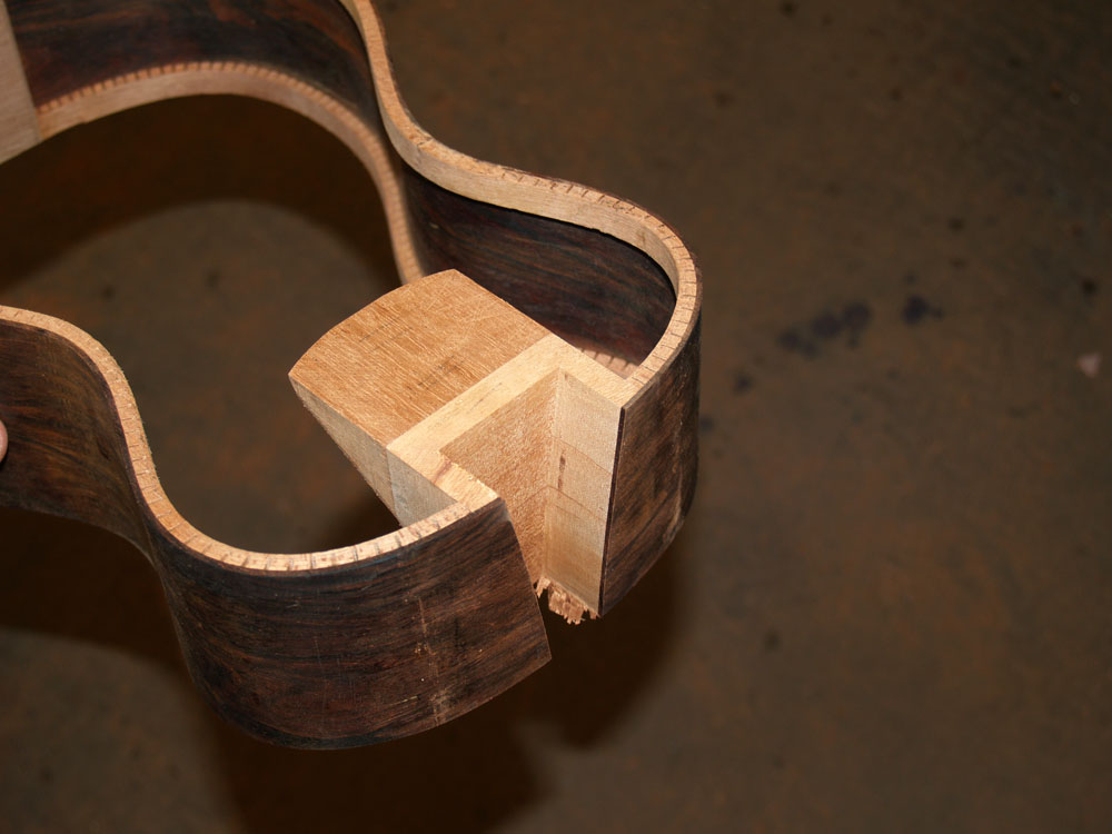
And another view. The heal of the neck will slip into this channel and sit on an adjustable tripod that will allow the angle of the neck to be changed and therefore the string to fretboard spacing. This way you get the action that you like.
 ( 73 ) 17-Nov-2011
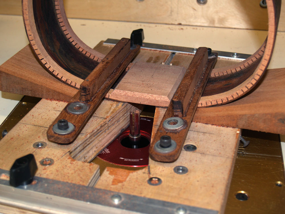
Here I am using the same fixture to route a channel for the tail graft.
 ( 74 ) 17-Nov-2011
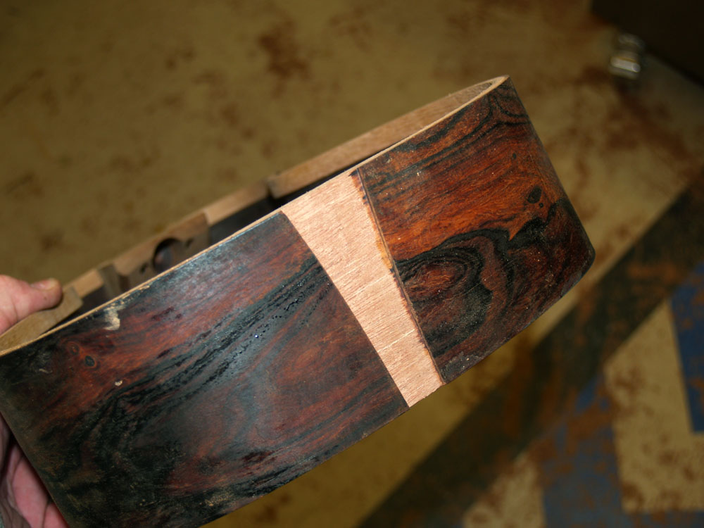
A decorative plate will go into this channel.
 ( 75 ) 17-Nov-2011
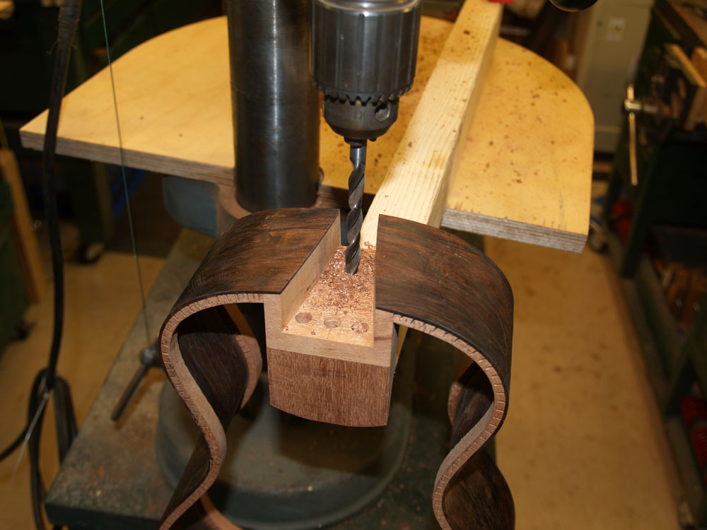
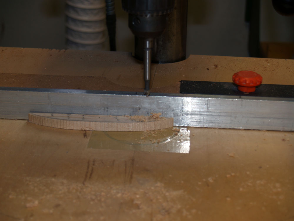
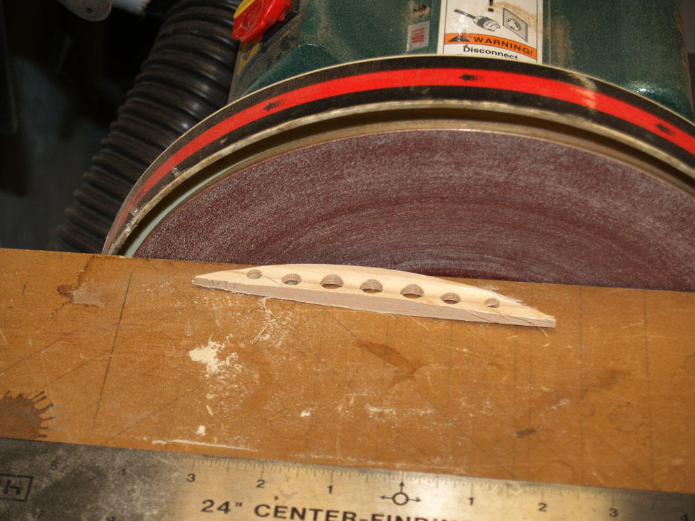
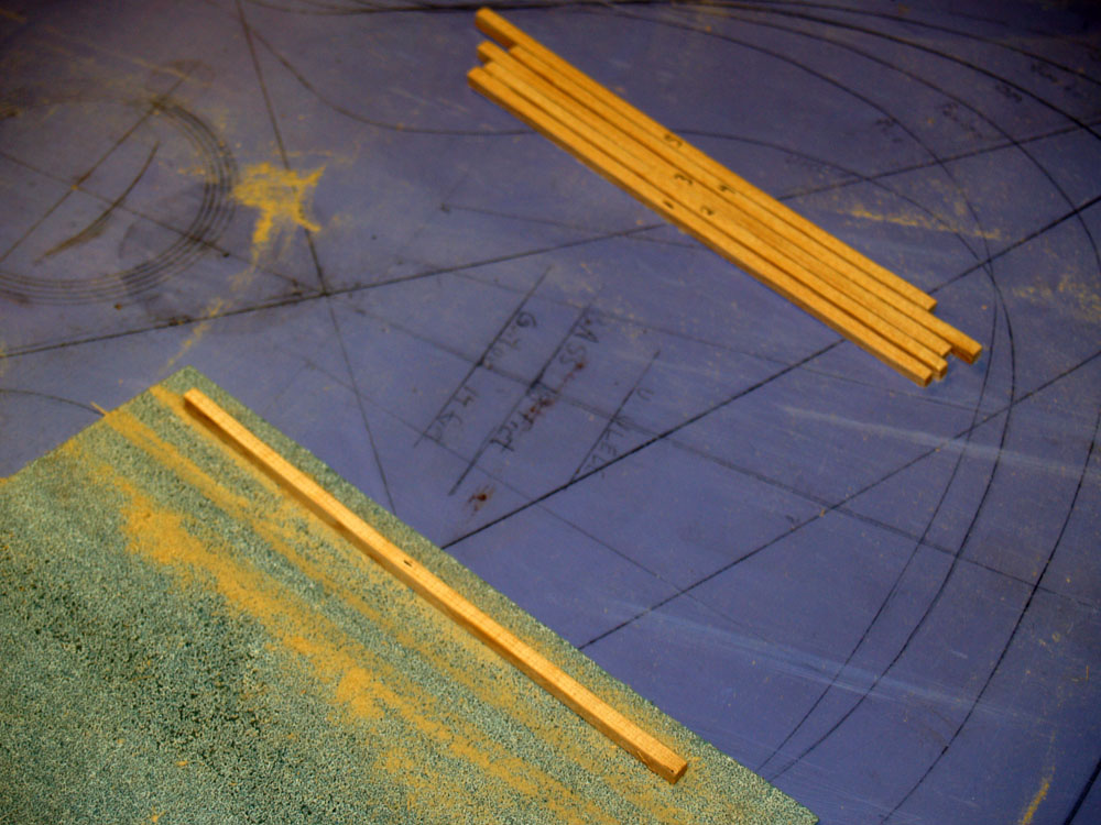
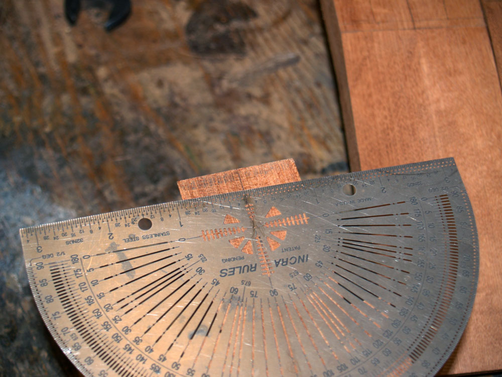
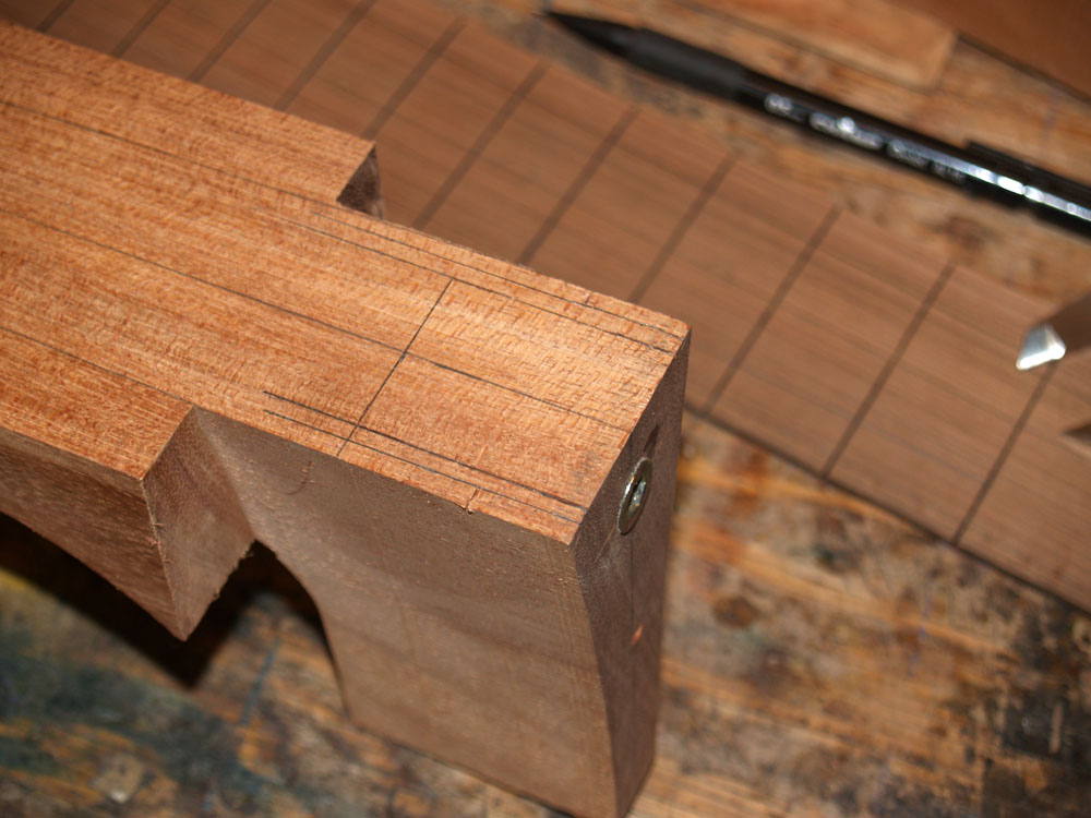
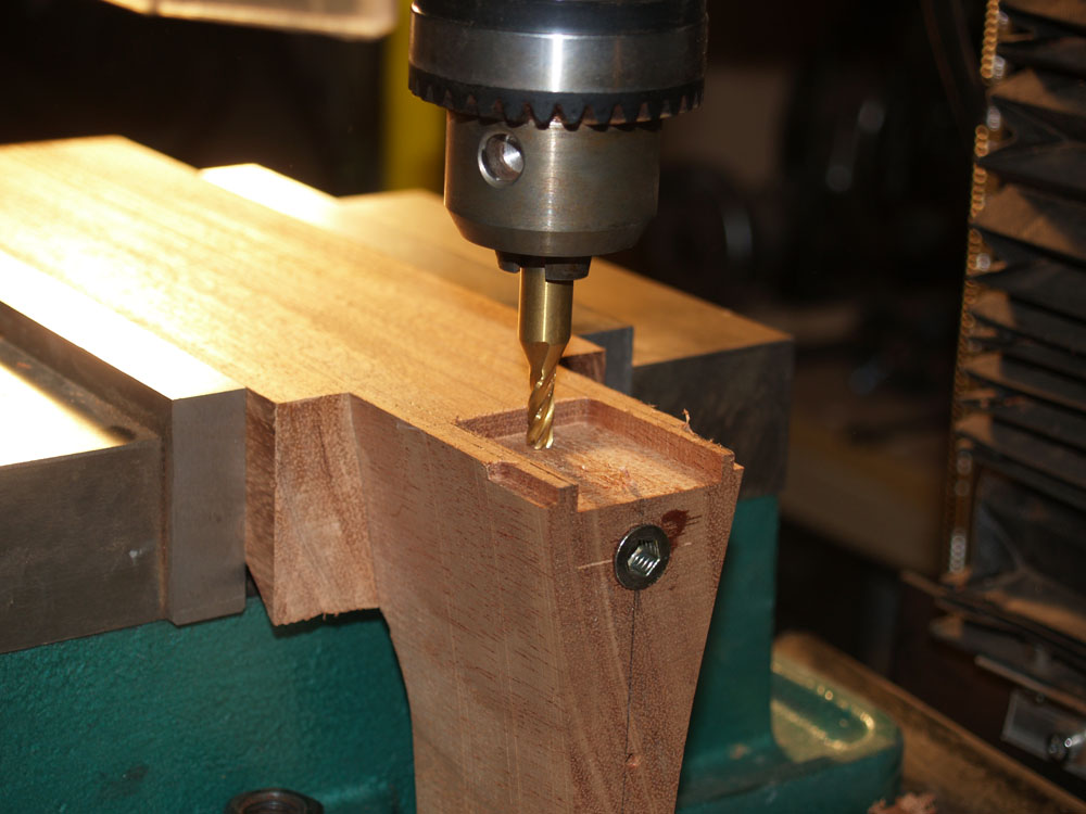
I have to drill four holes into the heal block to accommodate the neck attachment hardware. Gotta get these holes in just the right spots.
 ( 76 ) 17-Nov-2011
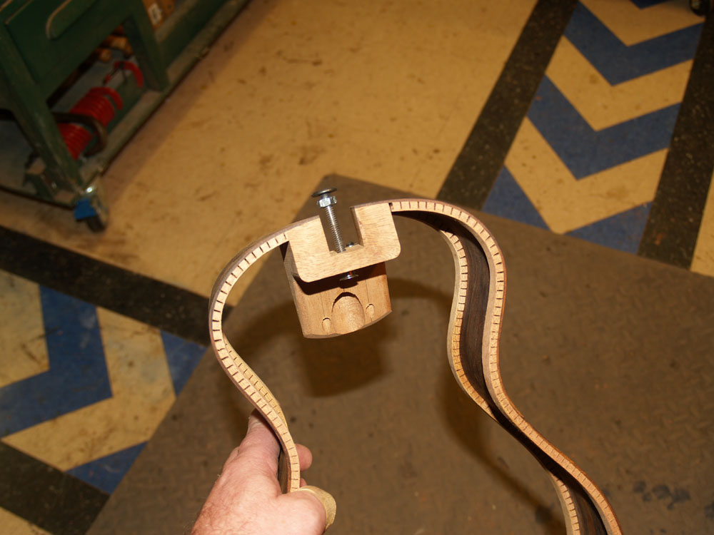
I install a wood insert into the heal block that will be used to adjust the neck angle. I am using this tool to make sure it is going in straight.
 ( 77 ) 17-Nov-2011
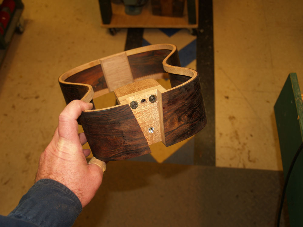
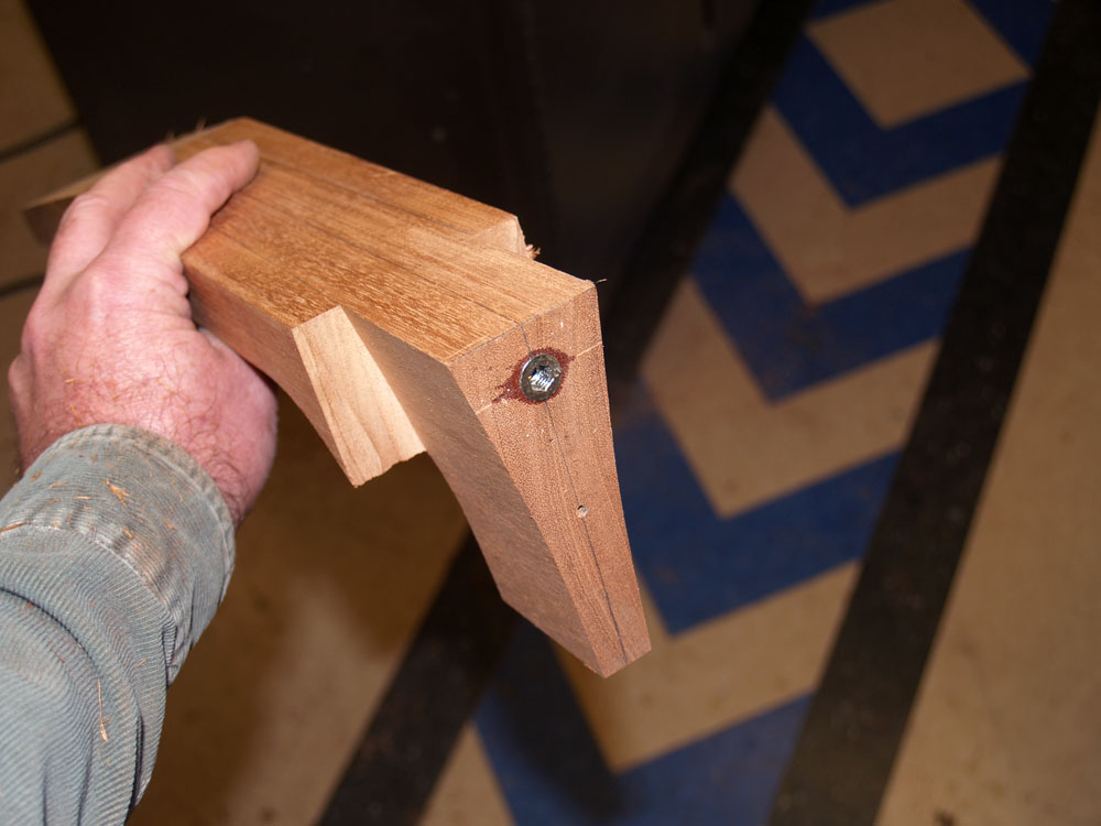
And two wood inserts and set screws make up the rest of the tripod. The center hole is used to bolt the neck to the body.
 ( 78 ) 17-Nov-2011
Now I turn my attention to making the braces that will support the back. Here I am using a template to lay out the braces on a piece of Sitka Spruce.
 ( 79 ) 17-Nov-2011
I use the bandsaw to rough out the braces.
 ( 80 ) 17-Nov-2011
And I use the disk sander to shape the bottom of the brace.
 Then I use the back form and sanding sheet to get a perfect match between the brace and the form.
 ( 82 ) 17-Nov-2011
My drill press is used to drill out the holes in the brace.
 ( 83 ) 17-Nov-2011
And then I use my router table to shape the brace into the shape of an I-beam. This arrangement will make the brace light and strong. Think about the shape of aircraft braces. Light strong and stiff, and they look cool too.
 ( 84 ) 17-Nov-2011
Finally I use the disk sander to shape the top of the brace. After all this I do a bit of hand sanding to finish the job. Each brace ends up being a tiny little sculpture.
 ( 85 ) 17-Nov-2011
Here I am fabricating the fan braces that will reenforce the top plate.
 ( 86 ) 17-Nov-2011
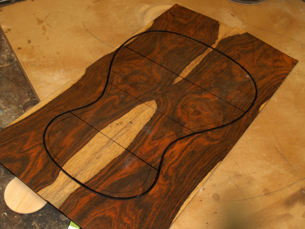
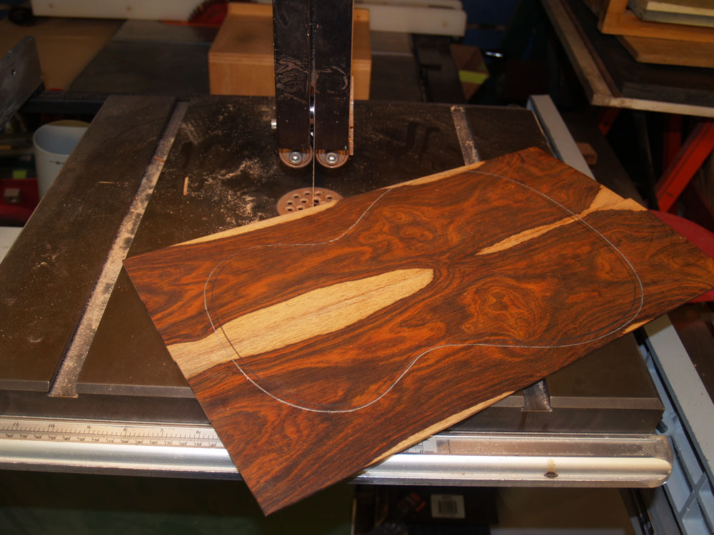
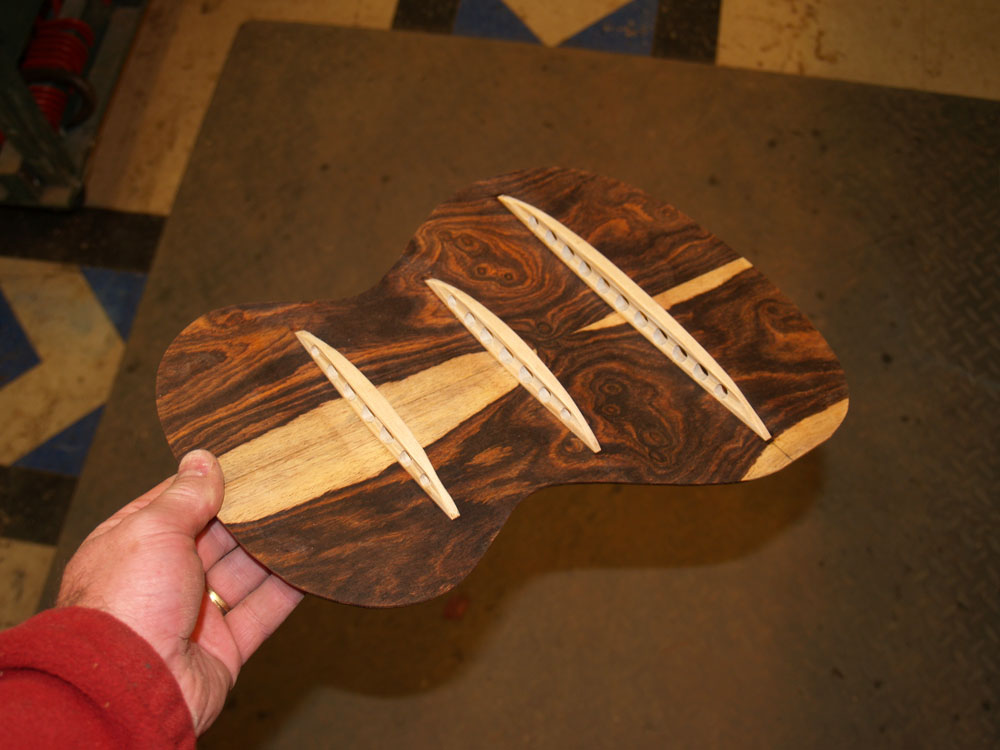
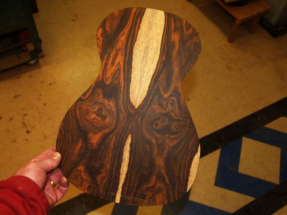
I use this template to layout the outline of the back on the back plate. Bonnie got to choose just how the back is going to look.
 ( 87 ) 17-Nov-2011
I use the bandsaw to cut out the back.
 ( 88 ) 17-Nov-2011
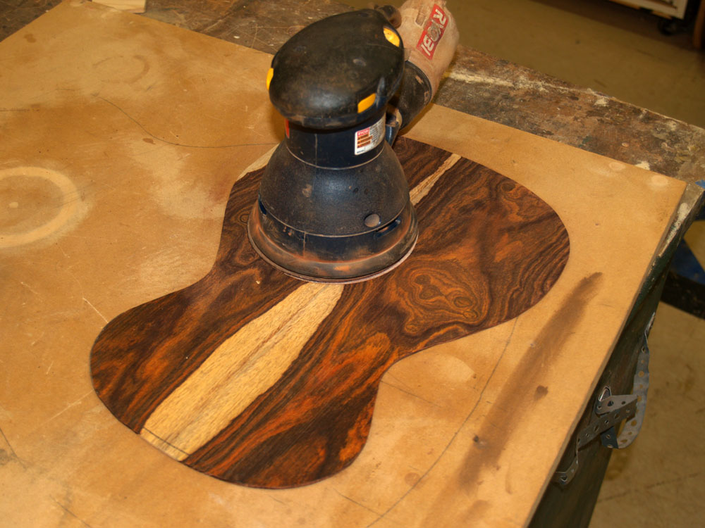
An orbital sander is used to sand the back smooth.
 ( 89 ) 17-Nov-2011
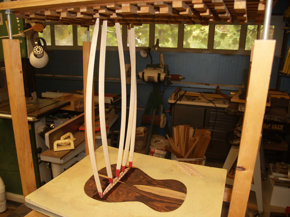
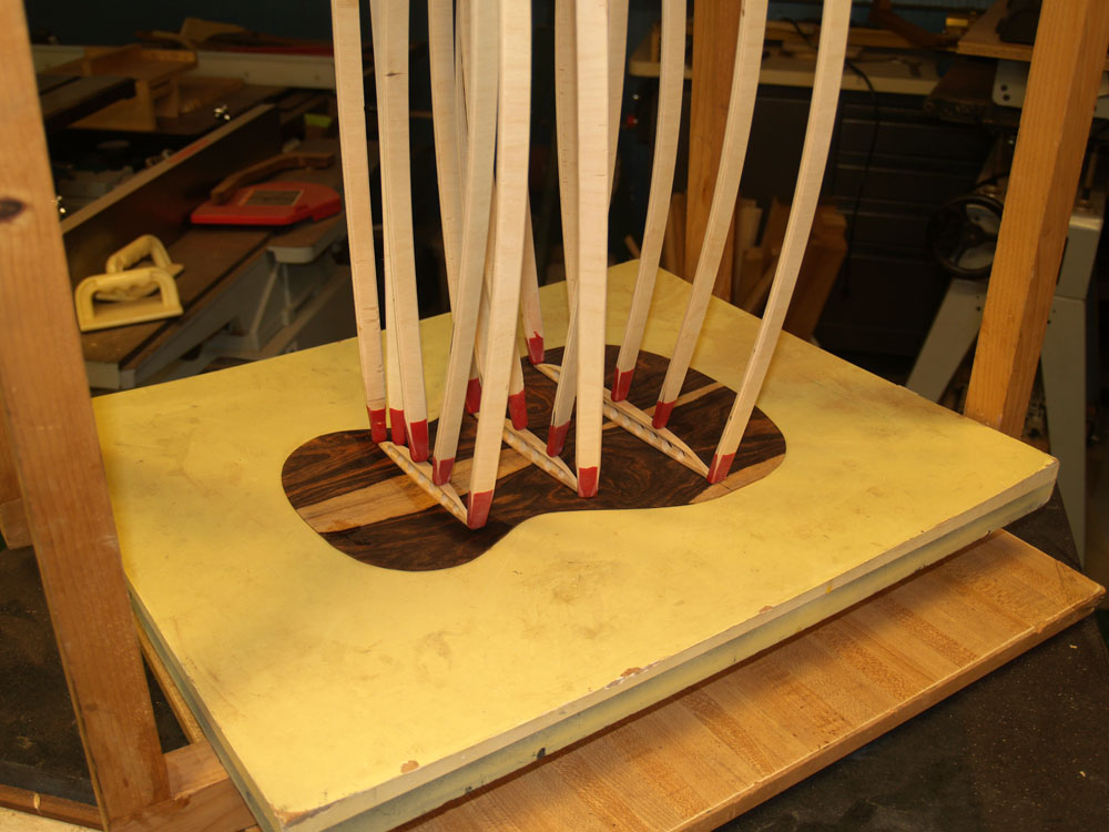
This is called a go-box. It is used with go-sticks to press the brace into the back. The back plate sits in the back form that the braces have been matched to.
 ( 90 ) 17-Nov-2011
When the braces have all been glued in place the back will take on the shape of the form.
 ( 91 ) 17-Nov-2011
The braces glued in place.
 ( 92 ) 17-Nov-2011
And a look at the back.
 ( 93 ) 17-Nov-2011
Now on to the neck. This is a mahogany neck blank that I created sometime in the past. It has had time to relax before it gets made into a neck. This is important because a freshly cut piece of wood this size has the potential to warp after it is first cut. Here I am using the belt sander to establish the surface that the fretboard will be glued to.
 ( 94 ) 17-Nov-2011
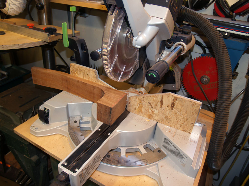
I use the miter saw to trim the end of the neck blank.
 ( 95 ) 17-Nov-2011
And then the belt sander again to establish the head stock surface.
 ( 96 ) 17-Nov-2011
I am going to route out the shape of the heal of the neck. I have attached this template to the end of the neck blank.
 ( 97 ) 17-Nov-2011
The neck blank and template then gets attached to this router fixture.
 ( 98 ) 17-Nov-2011
This big nasty router bit follows the shape of the template.
 ( 99 ) 17-Nov-2011
Another view of the heal still attached to the routing fixture. This routing fixture allows me to manipulate the neck while keeping my hands and fingers well away from the router bit. Safety is the most important thing in my shop.
 ( 100 ) 17-Nov-2011
And when I am finished the heal of the neck has the same shape as the channel that I routed into the heal block.
 ( 101 ) 17-Nov-2011
A bit more work on the neck blank requires carefully laying out the lines I will follow with the milling machine. This compass allows me to easily find the center line.
 ( 102 ) 17-Nov-2011
Here I have laid out the lines for the cantilever channel.
 ( 103 ) 17-Nov-2011
I use my milling machine to route the cantilever channel. This channel will hold a plate that reenforces the free floating portion of the fretboard. The two little side channels will help hide the seam between the fretboard and the body.
 ( 104 ) 17-Nov-2011
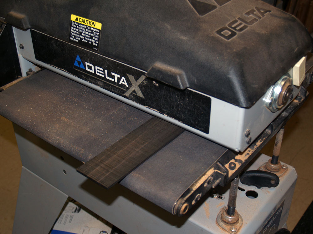
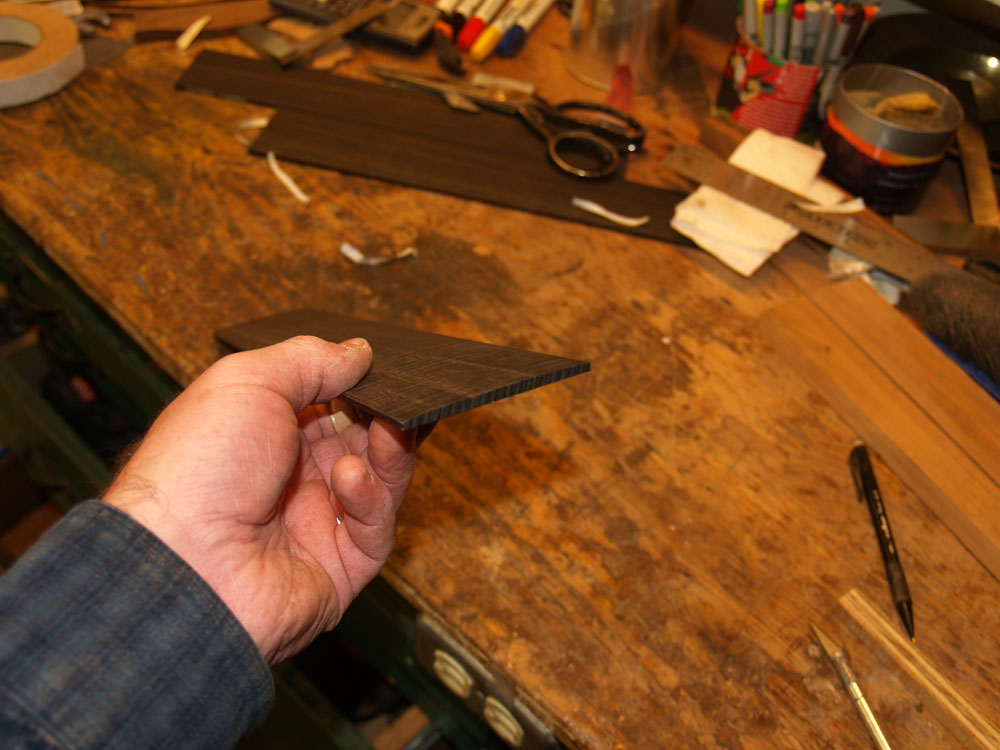
On to making the fretboard. Here I am using my drum sander to create an Ebony fretboard blank that is just the right thickness, about 1/8 inch thick.
 ( 105 ) 17-Nov-2011
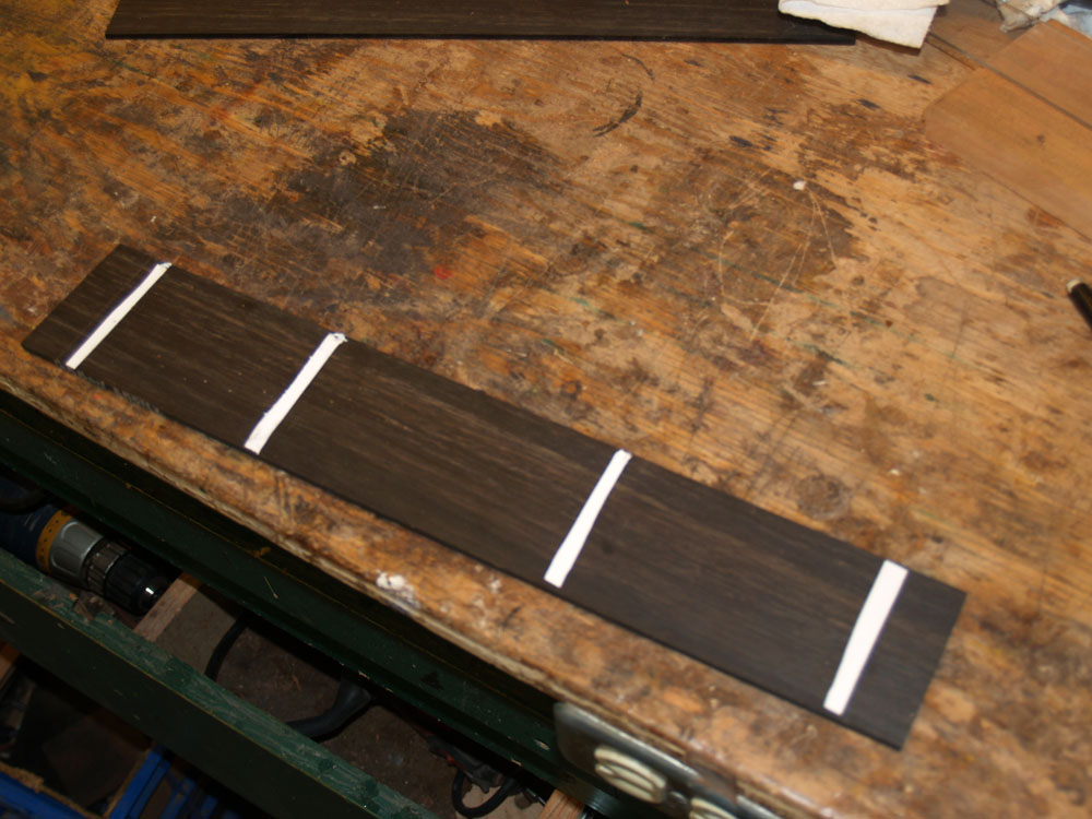
A few double sided strips of tape will attach the fretboard blank to the universal radiuser.
 ( 106 ) 17-Nov-2011
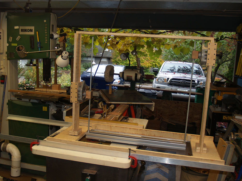
This Universal Radiuser is a machine of my own design
(although the idea is commonly held within the luthier community)
that help me create a compound radius on the top of the fretboard blank. This machine hold the fretboard blank at a precise height above the router bit while it swings back and forth with two arms of different length. The whole machine slides from right to left as the arms are swung back and forth. Think about a swing with two different lengths of rope. When I am finished the top of the fretboard will have a shape that is cut from the surface of a cone, a tighter radius near the point and a more gentle radius near the base. Since the fretboard is a taper this shape will allow the strings to have equal height from low to high.
 ( 107 ) 17-Nov-2011
Here you can see the bottom of the cross bar with the fretboard blank attached and the two arms of the radiuser.
 ( 108 ) 17-Nov-2011
Here is the router bit with the cross arm pulled out of the way.
 ( 109 ) 17-Nov-2011
When I am finished, in this case, the fretboard has a 20 inch radius at the 12th fret. My machine allows me to make a fretboard with a 7 to 21 inch radius. We like to put a radius on the fretboard because it fits the hand more comfortably than a flat board. Classical guitars typically have a flat fretboard though. The amount of radius is strictly a personal preference.
 ( 110 ) 17-Nov-2011
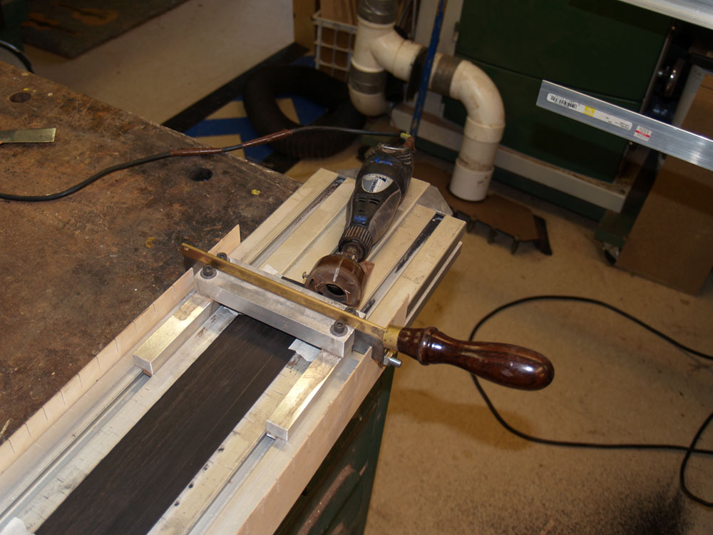
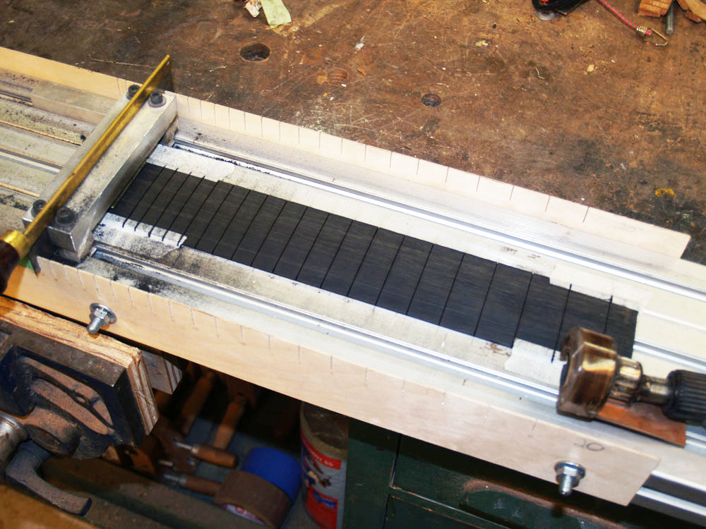
This is another machine I have created to cut the fret slots into the fretboard blank.
 ( 111 ) 17-Nov-2011
I use a set of templates to guide the position of the Dremel tool as it cuts the slots.