 ( 160 ) 25-July-2012
Now I spend a little time with some sandpaper cleaning up the interior side of the back. Wayne Henderson says this makes it easier for the notes to get out.
 ( 160 ) 25-July-2012
Now I spend a little time with some sandpaper cleaning up the interior side of the back. Wayne Henderson says this makes it easier for the notes to get out.
 ( 161 ) 25-July-2012
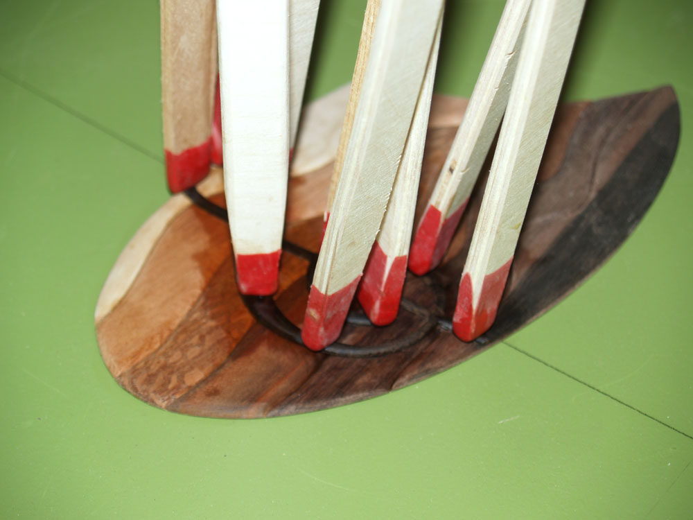
I round off the sound hole support ring.
 ( 162 ) 25-July-2012
After a bit of thought and waiting for inspiration to strike I start on the contra-rosette.
 ( 163 ) 25-July-2012
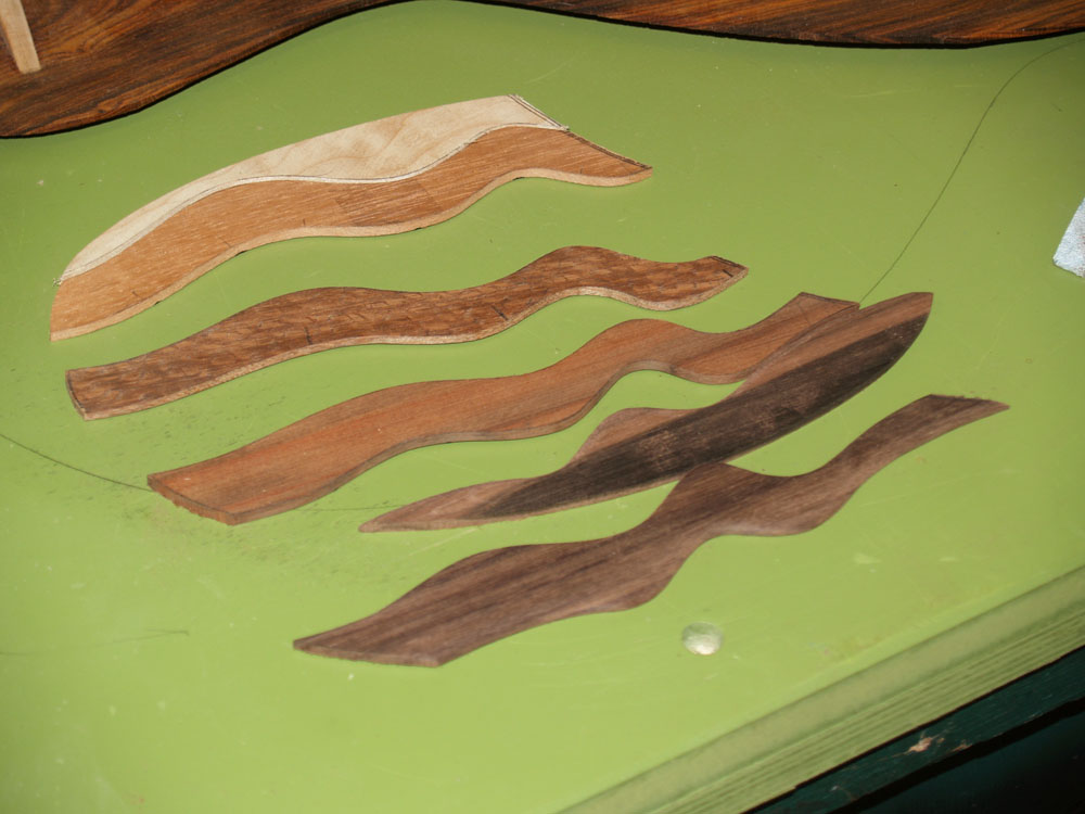
I am going for an embossed look on the this one.
 ( 164 ) 25-July-2012
I use my go-box to glue the various pieces together.
 ( 165 ) 25-July-2012
And then I glue the assembled rosette onto the interior side of the back.
 ( 166 ) 25-July-2012
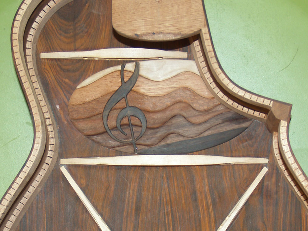
This is what the rosette / contra-rosette pair will look like.
 ( 167 ) 25-July-2012
And here is what I have created for the contra-rosette.
A bit of explanation : As you see, the Contra-Rosette is modeled on the Treble Clef. There are six pieces of wood making up the background which yields the five lines of the staff. The woods, starting from the top are Maple, Spanish Cedar, Lacewood, Walnut, Indian Rosewood, and Macassar Ebony. Notice, they go from light at the top, to dark at the bottom. This is supposed to be a metaphor for high frequency at the top to low frequency at the bottom. The Treble Clef itself is made from Zircote. The lines of the staff are designed with the intension of conveying the fluid nature of music, and the lines and are meant to suggest convergence at some distant horizon.
 ( 168 ) 25-July-2012
Since this is a cutaway I have glued a temporary support piece in the cutaway section.
 ( 169 ) 25-July-2012
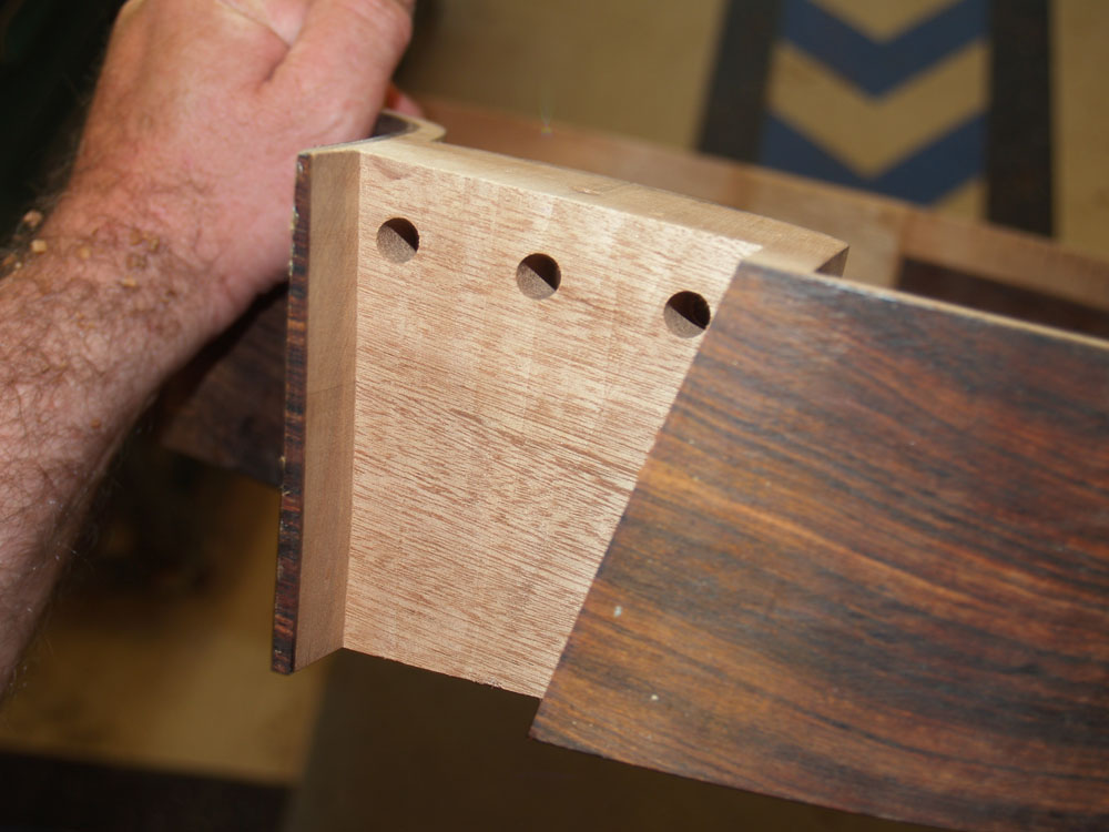
I use this special template guide to help me route out the heel channel in the body of the guitar.
 ( 170 ) 25-July-2012
After a bit of router work I have a channel cut one inch deep into the heel block. The channel will house all of the attachment and adjustment hardware for the neck.
 ( 171 ) 25-July-2012
Now I turn my attention the the neck. Here I am sanding flat the surface where the fretboard will be glued on.
 ( 172 ) 25-July-2012
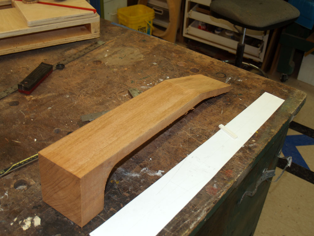
I have created a fretboard template to help me lay out the various parts of the neck.
 ( 173 ) 25-July-2012
I have created a headstock template to make sure all of the string placement will work.
 ( 174 ) 25-July-2012
Once I am confident in the lay out I trim the heel end of the neck blank.
 ( 175 ) 25-July-2012
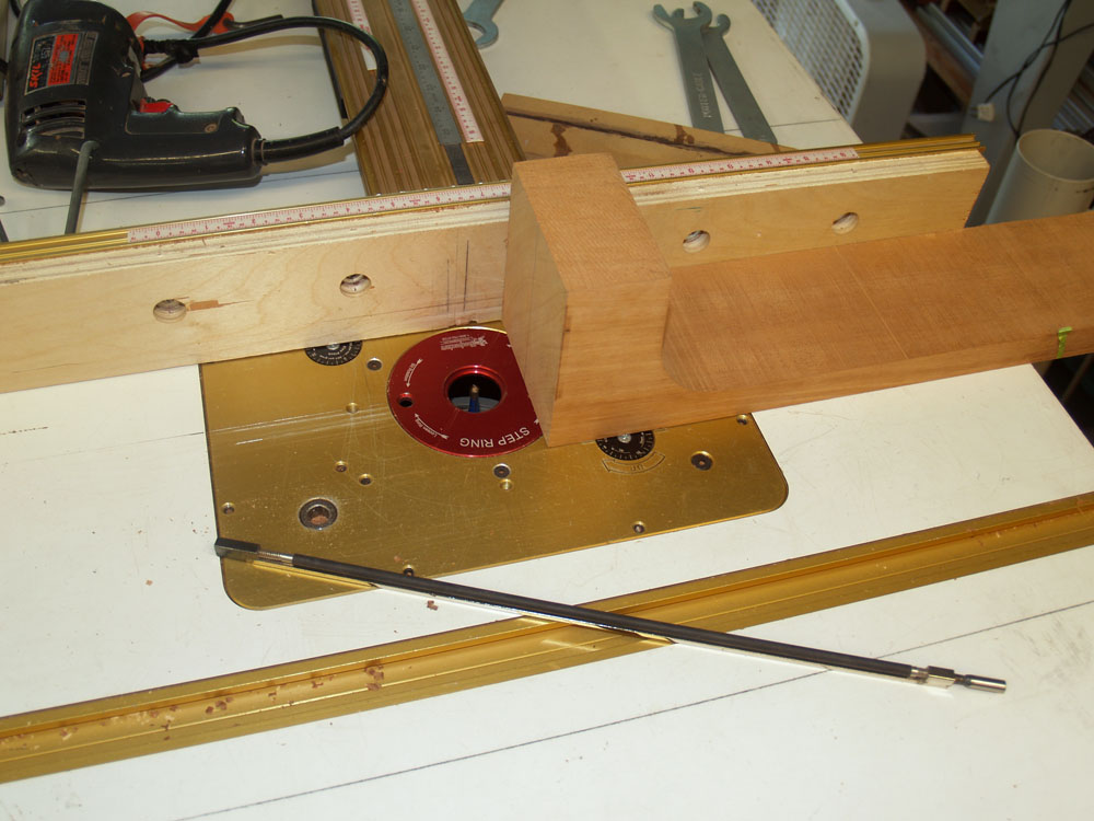
Then I use my router table to route out the channel for the truss rod.
 ( 176 ) 25-July-2012
My milling machine is used to create the details of the fretboard support and hiddy wing channels.
 ( 177 ) 25-July-2012
This picture shows the channel that will hold the fretboard's cantilever support plate.
 ( 178 ) 25-July-2012
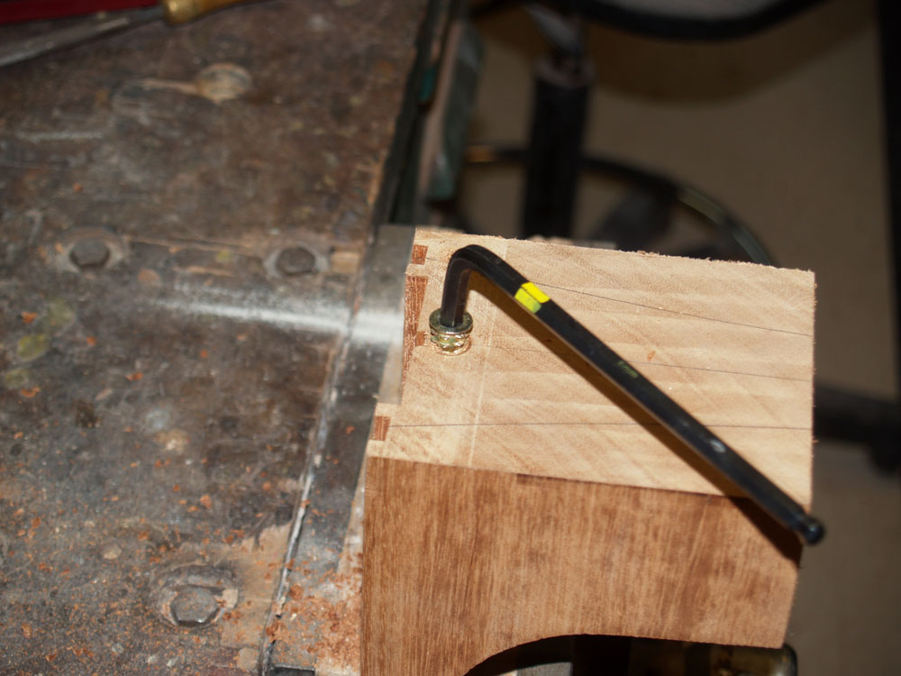
Here I am drilling the hole for the neck attachment bolt.
 ( 179 ) 25-July-2012
I use a 1/4-20 wood insert to provide a solid attachment point in the heel.
 ( 180 ) 25-July-2012
Here you can see all of the elements of the neck blank with the truss rod in place.
 ( 181 ) 25-July-2012
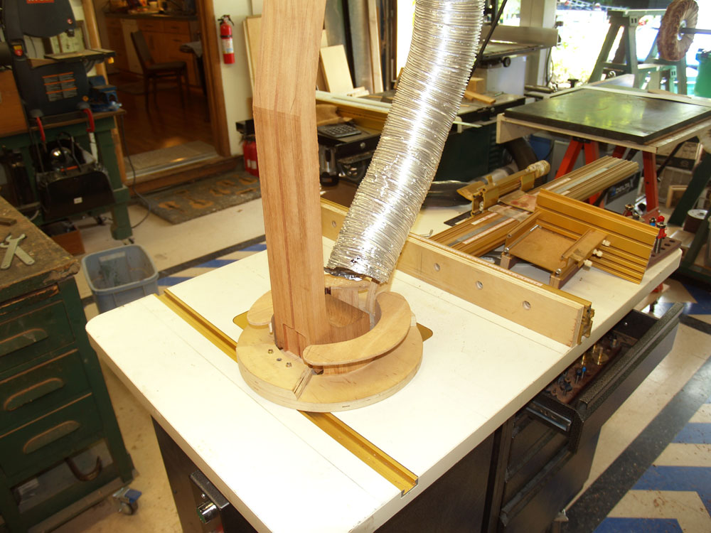
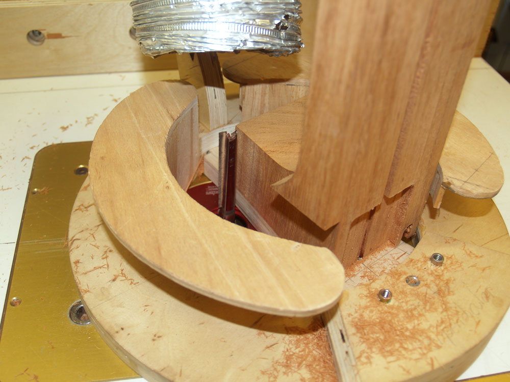
Now I am ready to shape the heel of the neck to match the heel channel I routed out in the body. I have built this special template tool to hold the neck blank while I route of the heel.
 ( 182 ) 25-July-2012
You can see the long router bit I use to shape the heel, big and scary.
 ( 183 ) 25-July-2012
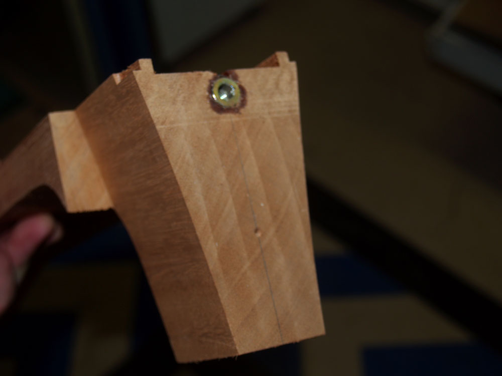
And this is what the heel looks like when I am finished.
 ( 184 ) 25-July-2012
Here I am installing the wood inserts in the heel channel that will mount the neck adjustment set screws.
 ( 185 ) 25-July-2012
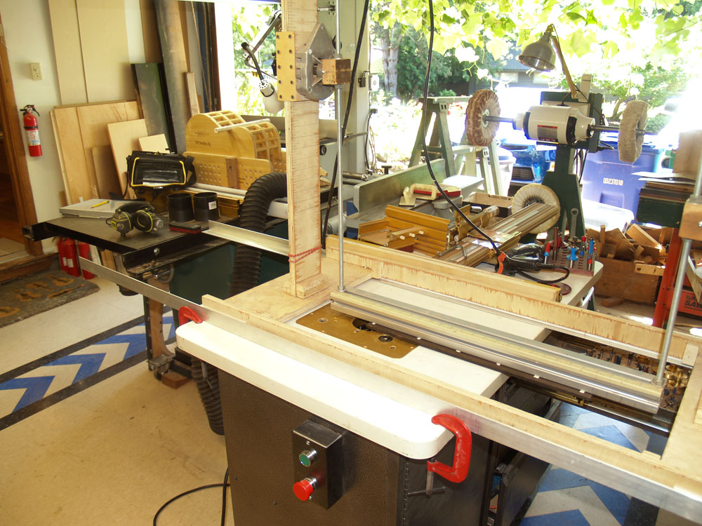
Now I am turning my attention the the fretboard. I have mounted the Macassar Ebony fretboard blank on the bottom of the Universal Radiusator cross beam.
 ( 186 ) 25-July-2012
The Universal Radiusator helps me shape the fretboard blank into a compound radiused fretboard. This is a machine that suspends the fretboard blank on a swing with two different length arms and then slides the assembly over a stationary router bit. By changing the length of the arms I can create a compound radius fretboard of any desired dimensions.
 ( 187 ) 25-July-2012
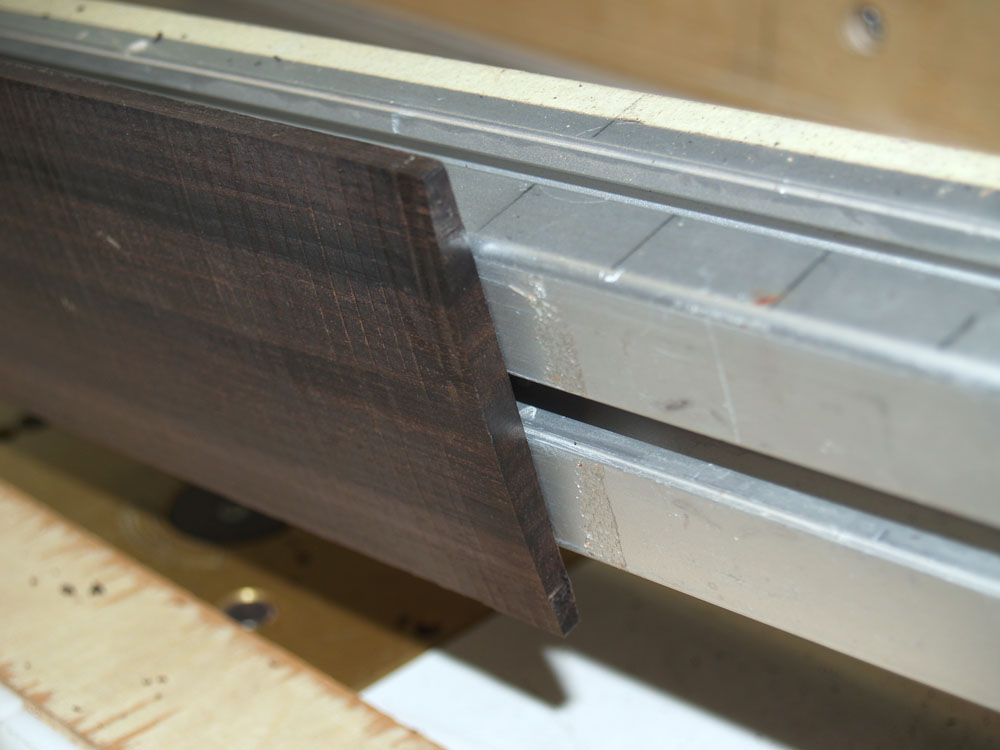
Here is a look at the end of the shaped fretboard.
 ( 188 ) 25-July-2012
After pulling the fretboard blank off of the machine I sand off the tooling marks.
 ( 189 ) 25-July-2012
In this picture I have laid out three different possible fretboard extensions.
 ( 190 ) 25-July-2012
Back to the router table to create the channel for the tail graft. I use the same template I used for the heel channel.
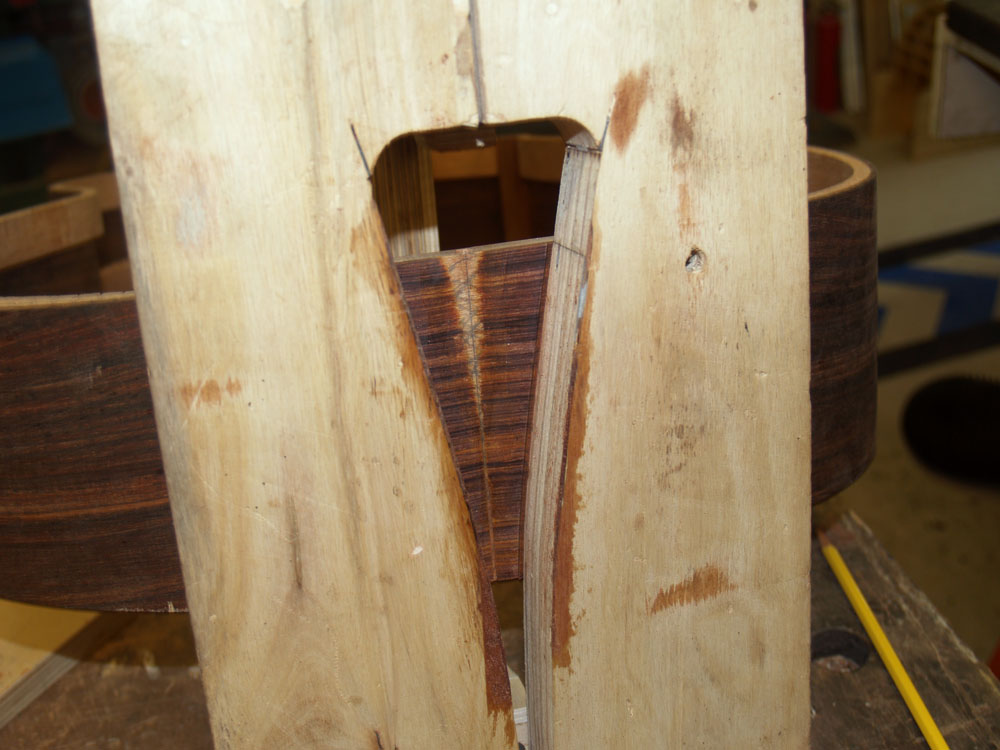 ( 191 ) 25-July-2012
This is a picture of the bottom of the template. The router bit follows the count our of the template, and I can control how deep the cut is by raising the height of the router bit on the table.
 ( 192 ) 25-July-2012
I cut this heel graft channel about 100 mils deep.
 ( 193 ) 25-July-2012
In this picture I am gluing a set of pinstriping to the edge of the graft channel.
 ( 194 ) 25-July-2012
And then I shape the Snakewood tail graft to fit into the channel.
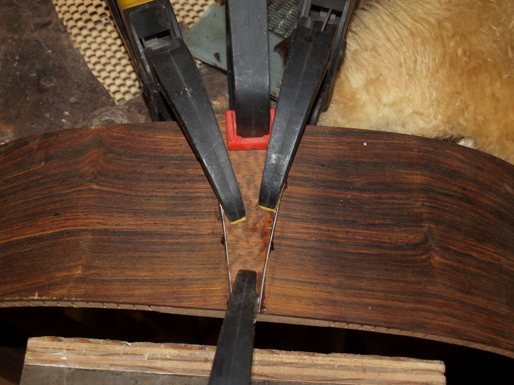 ( 195 ) 25-July-2012
A bit of glue and a few clamps are use to set the tail graft.
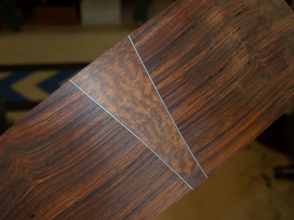 ( 196 ) 25-July-2012
After sanding everything flush, here is a look at the results. The binding will be made from the Snakewood and will be accented with the same pinstriping.
 ( 197 ) 25-July-2012
In this picture I an drilling the hole in the heel block that will have the wood insert installed for the User Adjustable Tilt Action Neck.
 ( 198 ) 25-July-2012
The wood insert is installed from the rear.
 ( 199 ) 25-July-2012
An small but important detail is the installation of the side reinforcing straps. The straps will help prevent the sides from splitting should the guitar ever experience a short sharp shock. You never drop your guitar do you?
 ( 200 ) 25-July-2012
I glue the straps onto the interior side of the rim where the braces meet the sides.
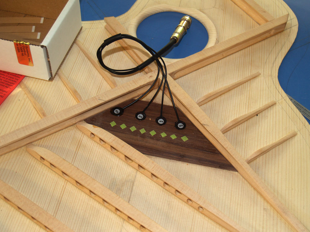 ( 201 ) 25-July-2012
We are installing a set of K&K Pure Classic Pickups
Here I have glued the piezoelectric paddles to the interior side of the bridge plate.
 ( 202 ) 25-July-2012
To prevent the pickup socket from banging around as I work on the guitar I have taped it down with some masking tape.
 ( 203 ) 25-July-2012
Once again I clean up the interior surfaces with a bit of sandpaper. Even though no one will see it, it is important to me that the interior be as good looking as the exterior.
 ( 204 ) 25-July-2012
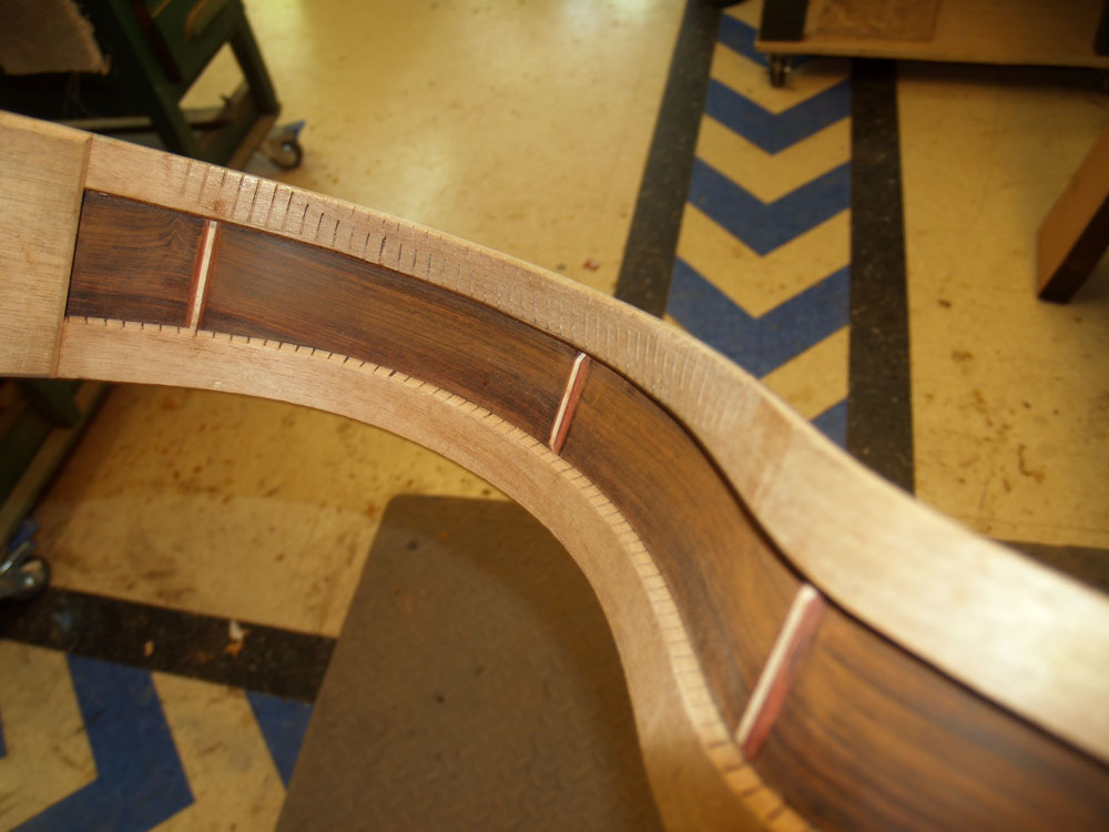
A look at the interior side of the rim with the straps in place.
 ( 205 ) 25-July-2012
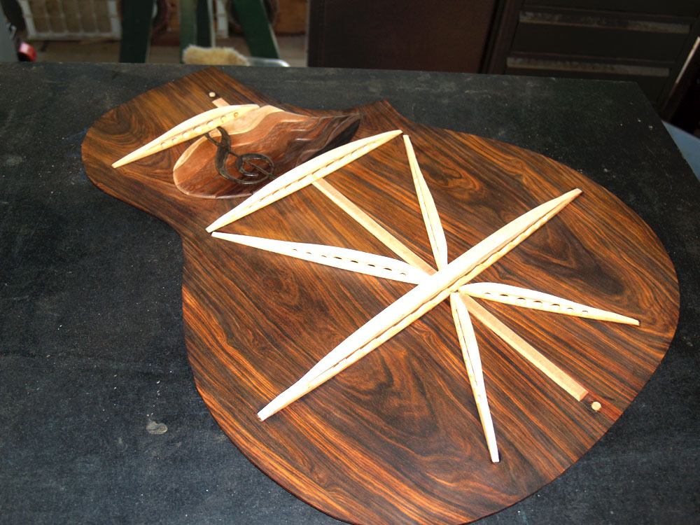
And after another trip to the go-box to install the reinforcing strips here is a look at the completed back plate.
 ( 206 ) 25-July-2012
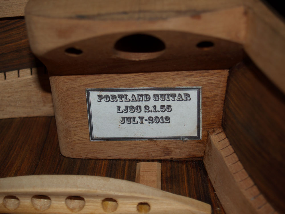
Before I glue the top and back onto the rim I attach an identifying label to the back of the heel block. I place this label in a position where you can see it if you look for it, but it doesn't jump out and scream at you through the sound hole. My thought is that after you have spent good money to purchase one of my guitars, you don't need me to advertise to you and yours. You know who you bought the instrument from.
 ( 207 ) 25-July-2012
I glue the back on first because I can clean up the glue squeeze out that would be visible through the sound hole. The top-to-rim glue joint isn't visible unless you pull out a mirror. I apply a thin layer of glue to the bottom edge of the rim. I want enough glue to make a good joint, but no more than is absolutely necessary. I call this a stoichiometric amount of glue. ( a bit of my geek flag flying I guess )
 ( 208 ) 25-July-2012
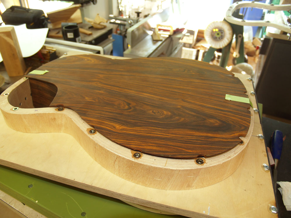
After placing the backplate on the rim I use a couple pieces of tape to make sure it doesn't slip out of position as press it into place with the compression flange.
 ( 209 ) 25-July-2012
Here is a view of the interior after the glue squeeze out has been cleaned up.
 ( 210 ) 25-July-2012
I let the joint set overnight. When it comes out of the form the backplate hangs over the rim by a quarter inch or so. I leave this extra band in the top and back plates just to insure that they will fit onto the rim without a problem. As much as I try for definition, precision, and accuracy, this is wood and it does shift about as you work it and the environment changes, so I like to leave a little wiggle room as I work.
 ( 211 ) 25-July-2012
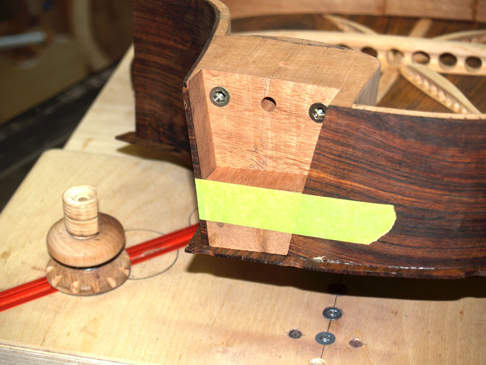
I will use a trim router with a guide wheel to trim the excess off of the back plate. Here I have installed a block in the heel channel prevent routing out the back plate in the channel.
 ( 212 ) 25-July-2012
I am using the trim router to trim off the backplate.
 ( 213) 25-July-2012
Now that the rim has the back glued on, thereby stabilizing it, I am making a template that will match the perimeter of the top in the area where I will trim away the bevel. I will use this template to mark out the top perimeter after the top is glued on.
 ( 214 ) 25-July-2012
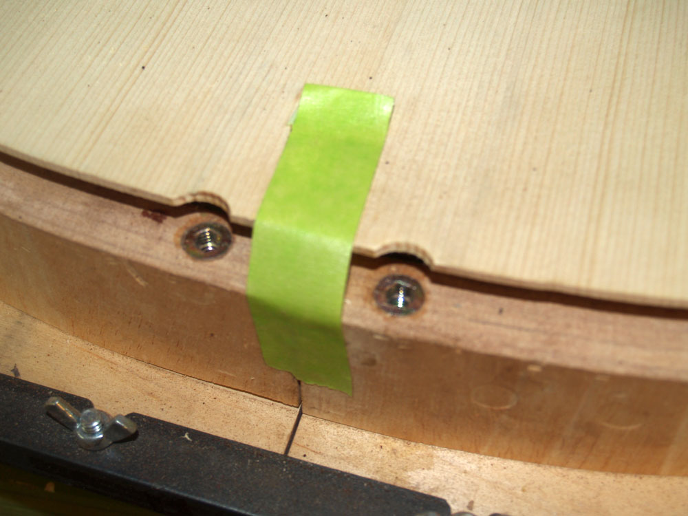
Once again I use a bit of tape to secure the top as I glue it on to the rim.
 ( 215 ) 25-July-2012
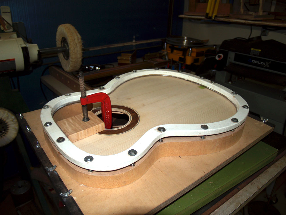
Here the compression flange pressing the top into place with a C-clamp pressing the heel block area.
 ( 216 ) 25-July-2012
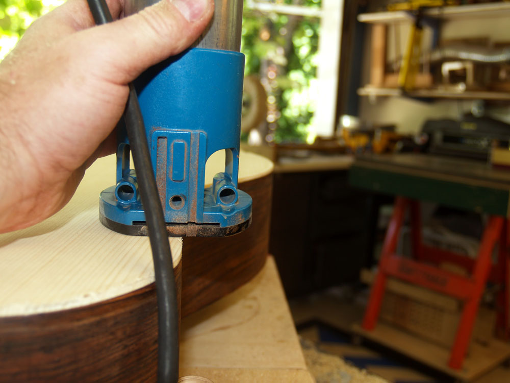
After a night to set, the trim router is used to trim away the excess.
 ( 217 ) 25-July-2012
I want the top to follow the rim a closely as possible.
 ( 218 ) 25-July-2012
This special fixture is guides a router to create a channel for the cantilever fretboard support plate.
 ( 219 ) 25-July-2012
A big router for a special job.
 ( 220 ) 25-July-2012
And here is the result. This channel will allow the neck to move freely while the support plate holds the fretboard steady.
 ( 221 ) 25-July-2012
And finally I place the top template in place to trace out the perimeter of the top.