 (105) 21-June-2012
I have joined a booked matched set of Cocobolo veneers and laid out a ring for the rosette.
 (105) 21-June-2012
I have joined a booked matched set of Cocobolo veneers and laid out a ring for the rosette.
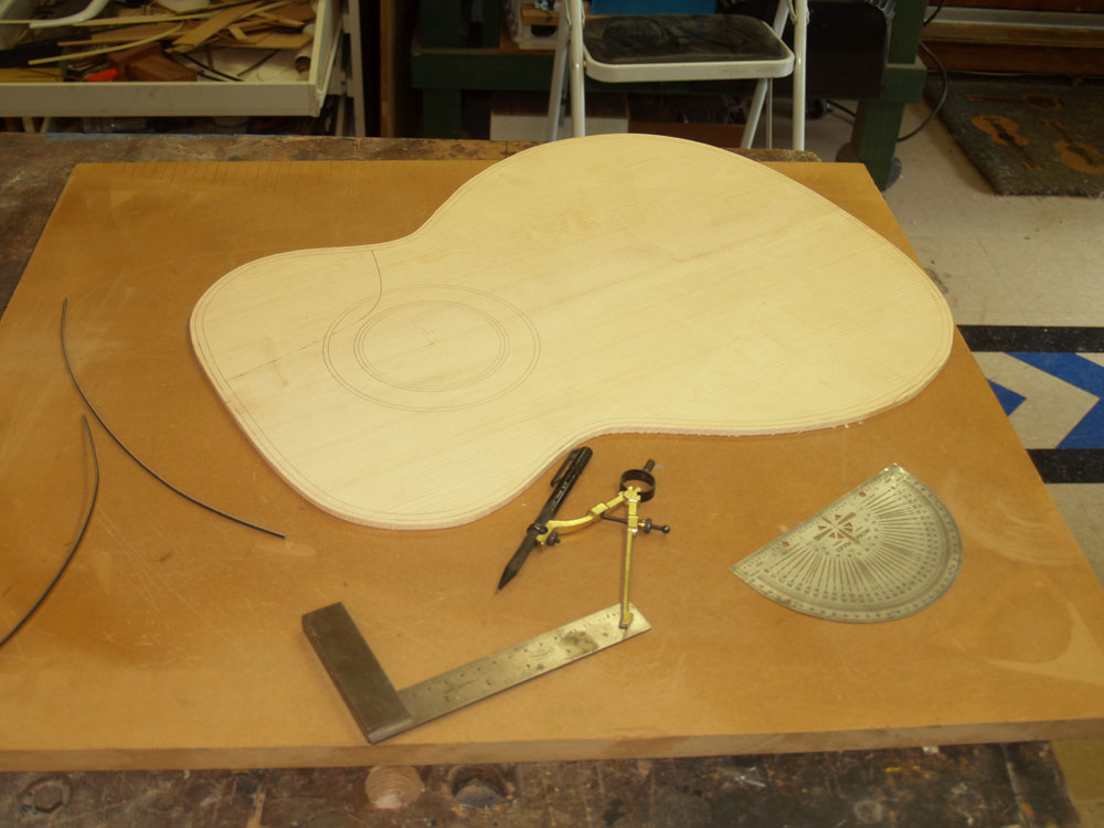 (106) 21-June-2012
And then laid out the rosette on the top plate.
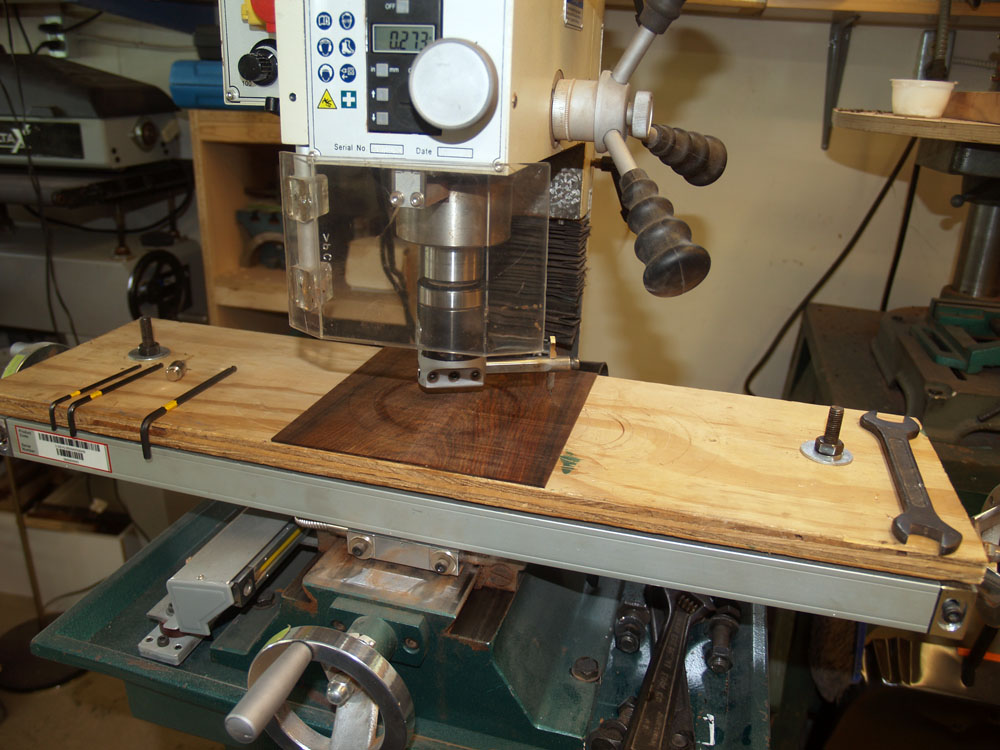 ( 107 ) 21-June-2012
I use a circle cutter on the milling machine to cut out the rosette.
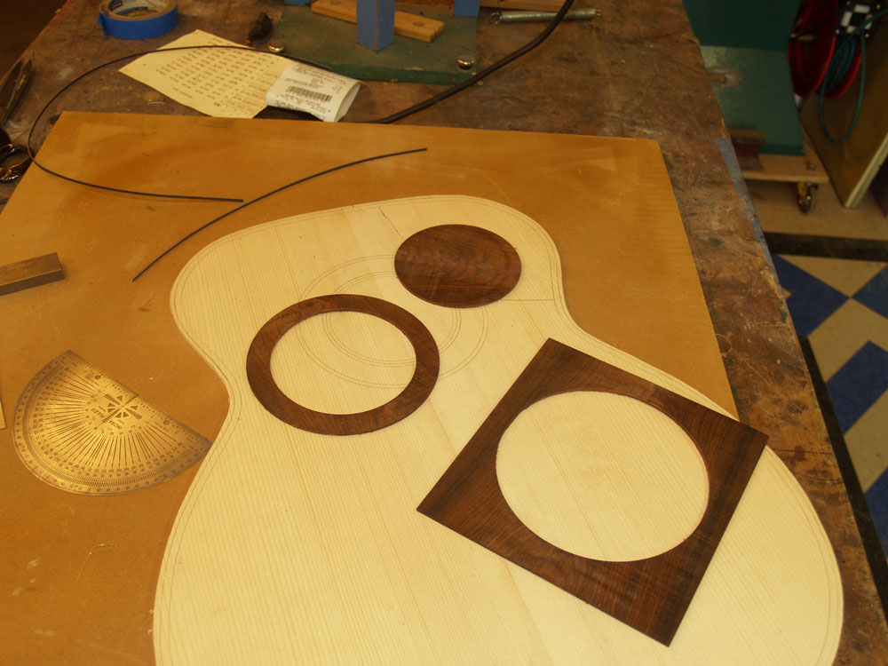 ( 108 ) 21-June-2012
The rosette and its jetsam.
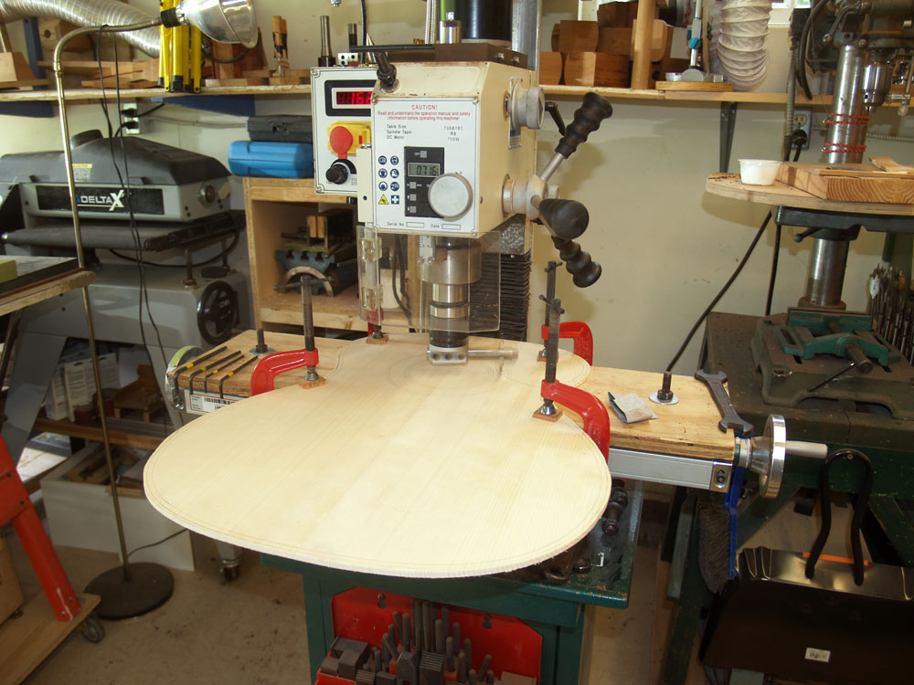 ( 109 ) 21-June-2012
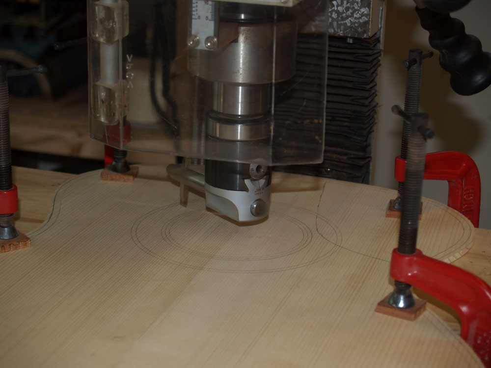
I use the circle cutter again to route out the channel in the top plate.
 ( 110 ) 21-June-2012
This circle cutter mounted in a boring mandrel lets me accurately cut the width and depth of the rosette channel.
 ( 111 ) 21-June-2012
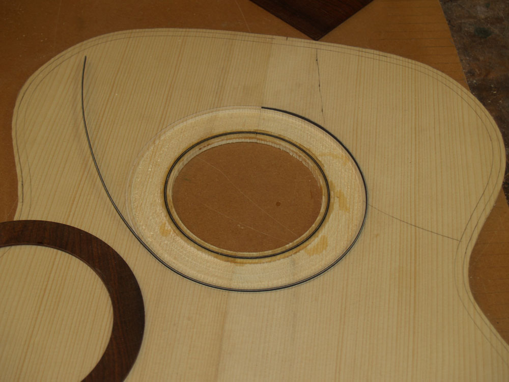
The Cocobolo ring neatly drops into the channel.
 ( 112 ) 21-June-2012
I have also routed two narrow channels that will hold a set of pinstriping.
 ( 113 ) 21-June-2012
A bit of glue will secure the rosette.
 ( 114 ) 21-June-2012
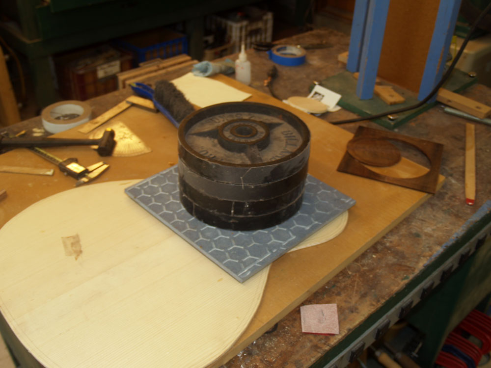
The rough rosette pieces sit proud of the surface.
 ( 115 ) 21-June-2012
To make sure they are firmly seated I weight them down.
 ( 116 ) 21-June-2012
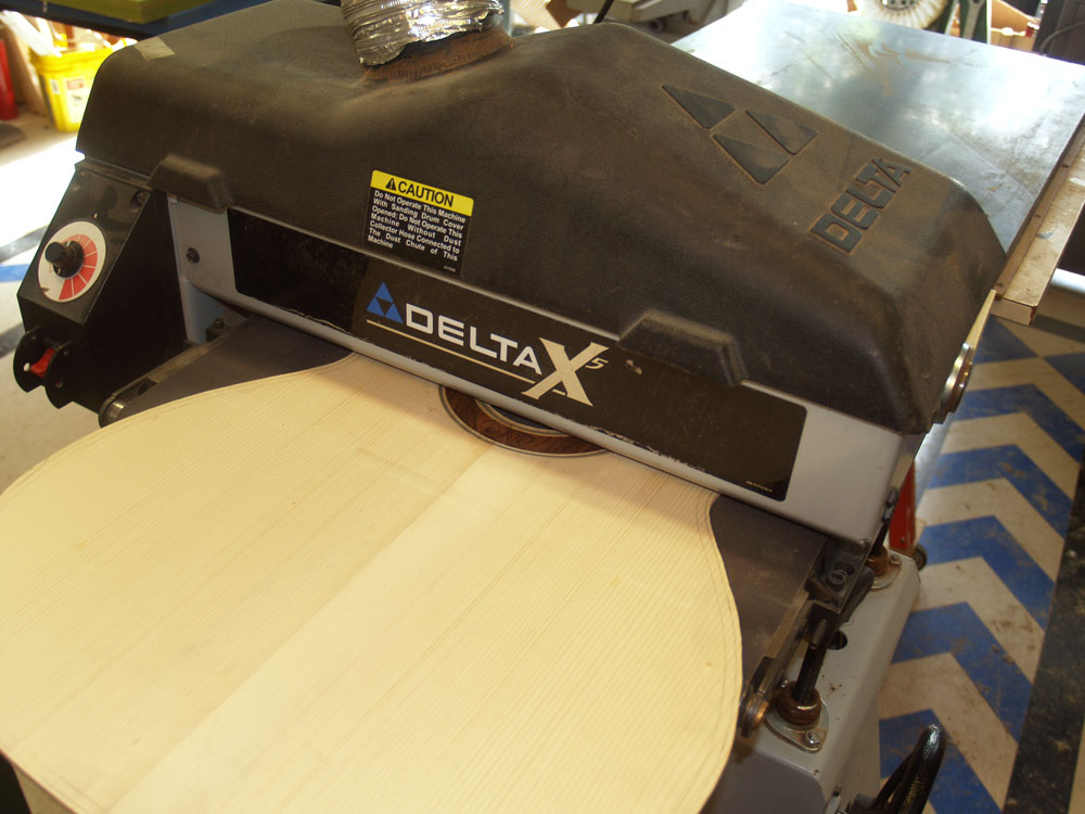
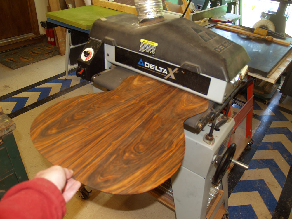
I use my drum sander to level everything off.
 ( 117 ) 21-June-2012
And in the end we have a handsome rosette. Once I am happy with the front of the sound plate I use the drum sander again to dimension it to about 110 mils.
 ( 118 ) 21-June-2012
I also sand the back plate to about 100 mils thick.
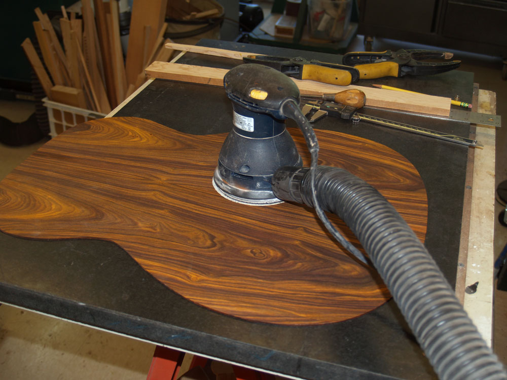 ( 119 ) 21-June-2012
A little bit of palm sanding removes the sanding marks.
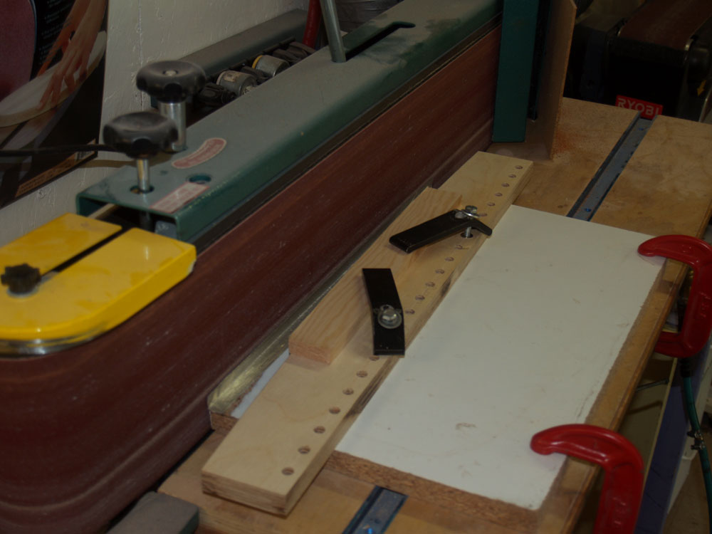 ( 120 ) 21-June-2012
Now I am turning my attention to the braces for the top and back plates. I use a template guide to sand the bottom of each brace.
 ( 121 ) 21-June-2012
A little bit of hand sanding makes sure the bottom of the braces match the curve of the forms.
 ( 122 ) 21-June-2012
Here I am checking the fit of the braces.
 ( 123 ) 21-June-2012
I use the band saw to rough out the shape of the top of the braces.
 ( 124 ) 21-June-2012
I use my oscillating sander to dimension the height of the main X-braces.
 ( 125 ) 21-June-2012
Here I am tracing out the interior of the rim onto the back plate.
 ( 126 ) 21-June-2012
And then I layout the position of each brace onto the backplate.
 ( 127 ) 21-June-2012
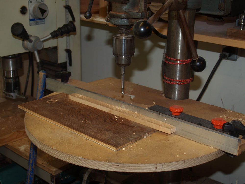
I use set of Forstner bits on the drill press to make holes in the braces.
 ( 128 ) 21-June-2012
Lots of holes. Since the holes lie on the neutral axis of the braces, they reduce the mass of the braces while maintaining their stiffness.
 ( 129 ) 21-June-2012
Here I am laying out the position of the braces on the top plate.
 ( 130 ) 21-June-2012
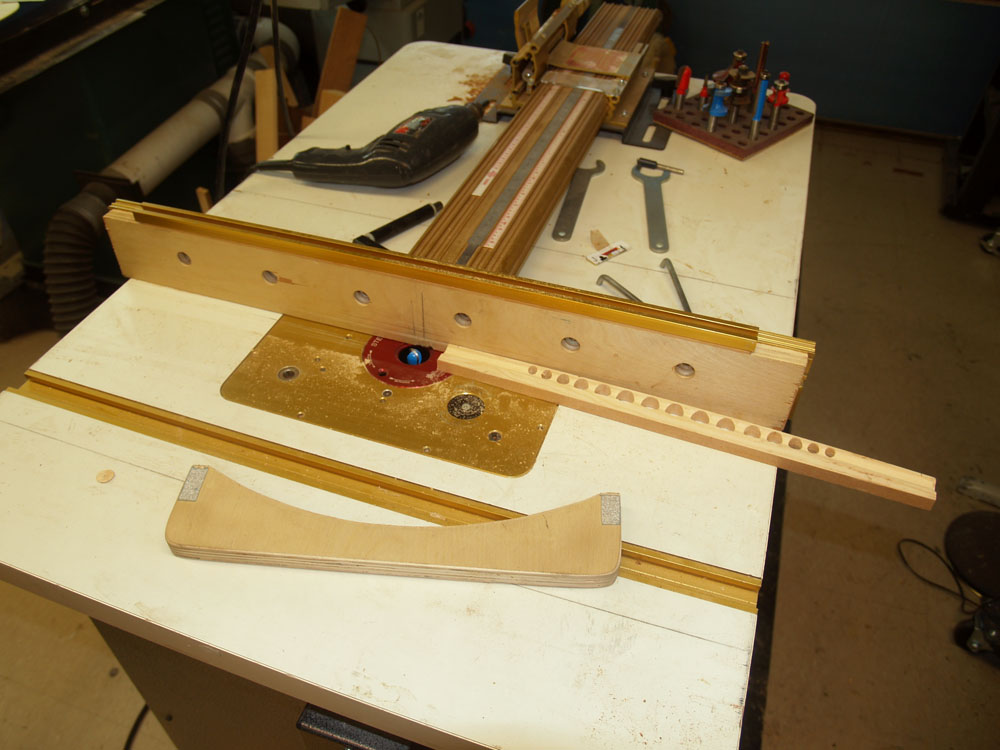
To further reduce the mass of the braces I use the router table to route out the side channels.
 ( 131 ) 21-June-2012
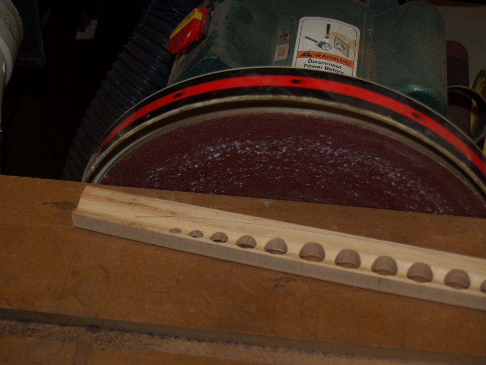
I end up with a brace that is shaped like an I-beam with the web cut out. Technically this results in a brace with a high moment of inertia and low mass. Stiff and light.
 ( 132 ) 21-June-2012
The disk sander is used to shape the top and sides of the braces.
 ( 133 ) 21-June-2012
I end up with a graceful cool looking brace that has all of the desired properties I am after.
 ( 134 ) 21-June-2012
Here I have laid out the braces on the back.
 ( 135 ) 21-June-2012
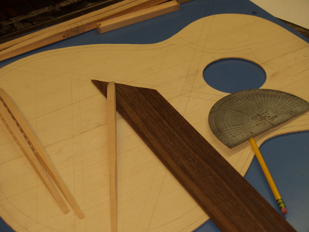
In this picture I am laying out the Indian rosewood bridge plate.
 ( 136 ) 21-June-2012
I bevel and shape the the bridge plate on a disk sander.
 ( 137 ) 21-June-2012
Here I am shaping a finger brace on the disk sander.
 ( 138 ) 21-June-2012
I use my bandsaw to create the lap joints in the main x-braces.
 ( 139 ) 21-June-2012
I carefully cut out the channel in each brace.
 ( 140 ) 21-June-2012
These two channels are matched at their proper angle.
 ( 141 ) 21-June-2012
When the braces are joined they make a tight and strong joint.
 ( 142) 21-June-2012
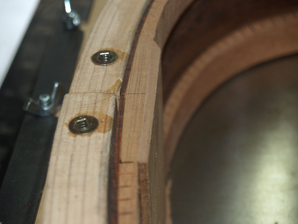
A small detail requires beveling the tail plate to match the kerfing.
 ( 143 ) 21-June-2012
I use a fiducial button to let me position the top and back plate on the rim.
 ( 144 ) 21-June-2012
I put a small drop of glue in the end of the button and then position the rim on the plate. After the glue dries the button sticks to the plate. I can now repeatedly place the plates on the rim exactly in position.
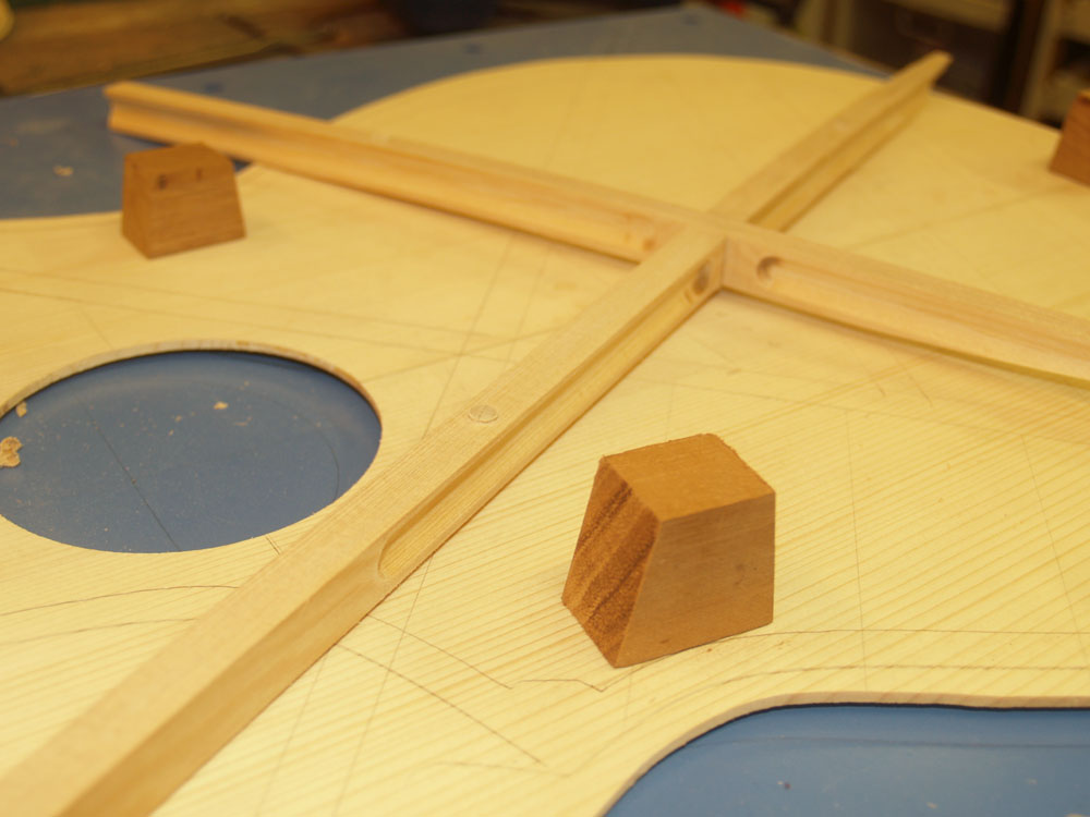 ( 145 ) 21-June-2012
I need to trim the X-brace so they will butt up against the kerfing. To help position the rim I use a set of guide blocks.
 ( 146 ) 21-June-2012
And to position the X-braces I use another set of fiducial buttons.
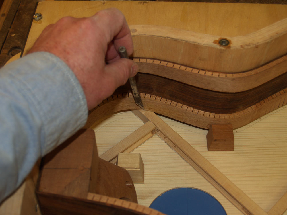 ( 147 ) 21-June-2012
Once the rim is precisely positioned I use a sharp blade to score the brace at the kerfing. I then cut off the ends of the braces at the score marks.
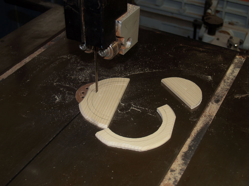 ( 148 ) 21-June-2012
After laying out the sound hole I cut it out on the bandsaw
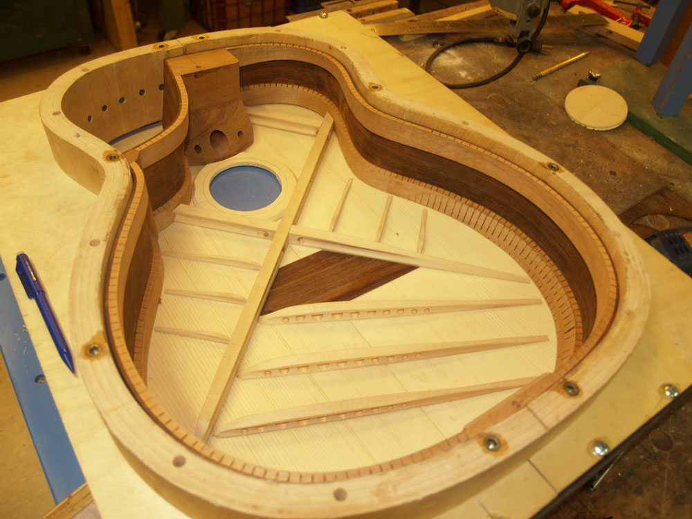 ( 149 ) 21-June-2012
And in the end the rim snuggly fits up against the braces.
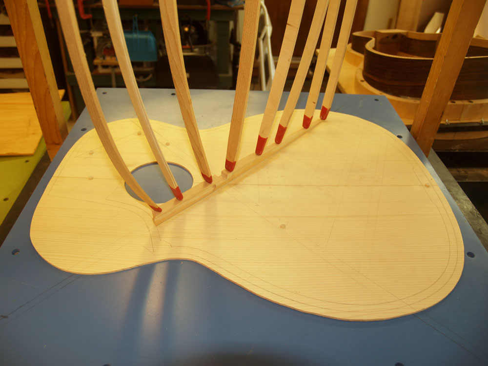 ( 150 ) 21-June-2012
Now with all of the braces made I start to glue them in place. I use a go-box to press the braces in place.
 ( 151 ) 21-June-2012
Lots of go-sticks.
 ( 152 ) 21-June-2012
Lots and lots of go-sticks. That arc in the top plate of the go-box is not an artifact of the camera lens.
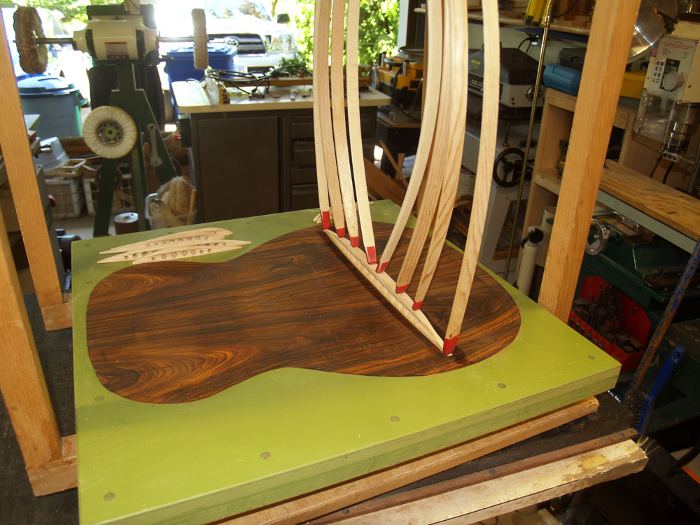 ( 153 ) 21-June-2012
The back braces get the same treatment.
 ( 154 ) 21-June-2012
I make sure that the braces make near perfect contact with the plate. I really want a good joint here.
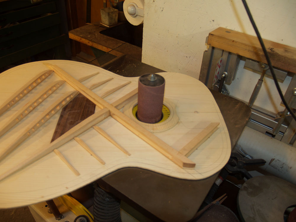 ( 155 ) 21-June-2012
The sound hole gets trimmed up on the oscillating sander.
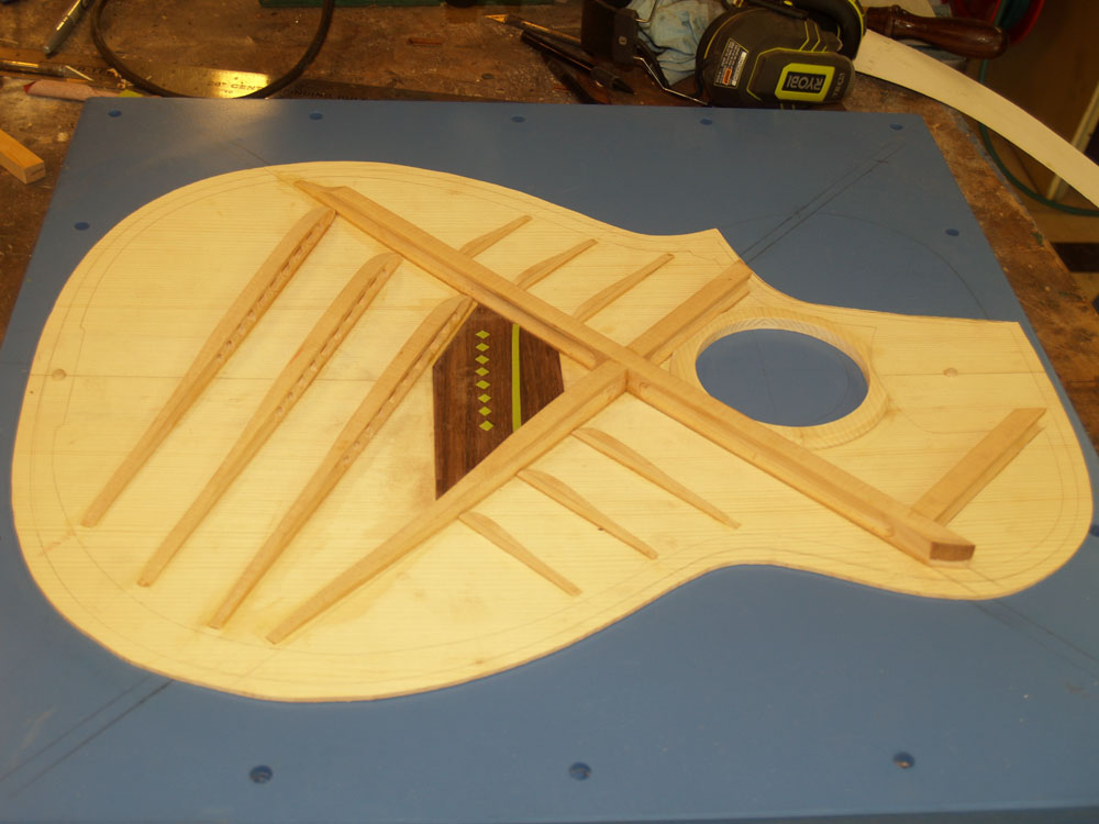 ( 156 ) 21-June-2012
A look at the top plate with the braces in place and the cutaway removed.
 ( 157 ) 21-June-2012
Another look.
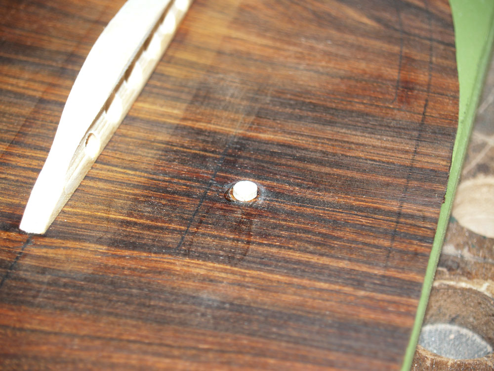 ( 158 ) 21-June-2012
The back plate gets a set of fiducial buttons.
 ( 159 ) 21-June-2012
A look at the back plate after the cutaway is removed.